


3-15
1
2
3
4
5
6
Chapter 3 Machine setting
Setting a AUTO Power-off
When no operation has been performed for the set time,
the power supply is automatically turned “OFF”.
1
Press
(MENU)
(twice)
in LOCAL.
• MACHINE SETUP MENU will be displayed.
2
Press
to select “AUTO POWER
OFF”, and press the
key.
3
Press
to select a set value, and
press the
key.
•
Set Value
: none, 10 to 600min
4
Press the
key several times to
end the setting.
Setting Top Blower
Set the operation of the top blower in print.
Turn the top blower setting “ON”, and you can set the
strength for the blower.
1
Press
(MENU)
(twice)
in LOCAL.
• MACHINE SETUP MENU will be displayed.
2
Press
to select “Top blower”,
and press the
key.
3
Press
to select “ON”, and press
the
key.
ON : You can choose the air volume of the blower.
OFF : The top blower does not work while printing
process. Proceed to step 6.
4
Press
to select “STRENGTH”,
and press the
key.
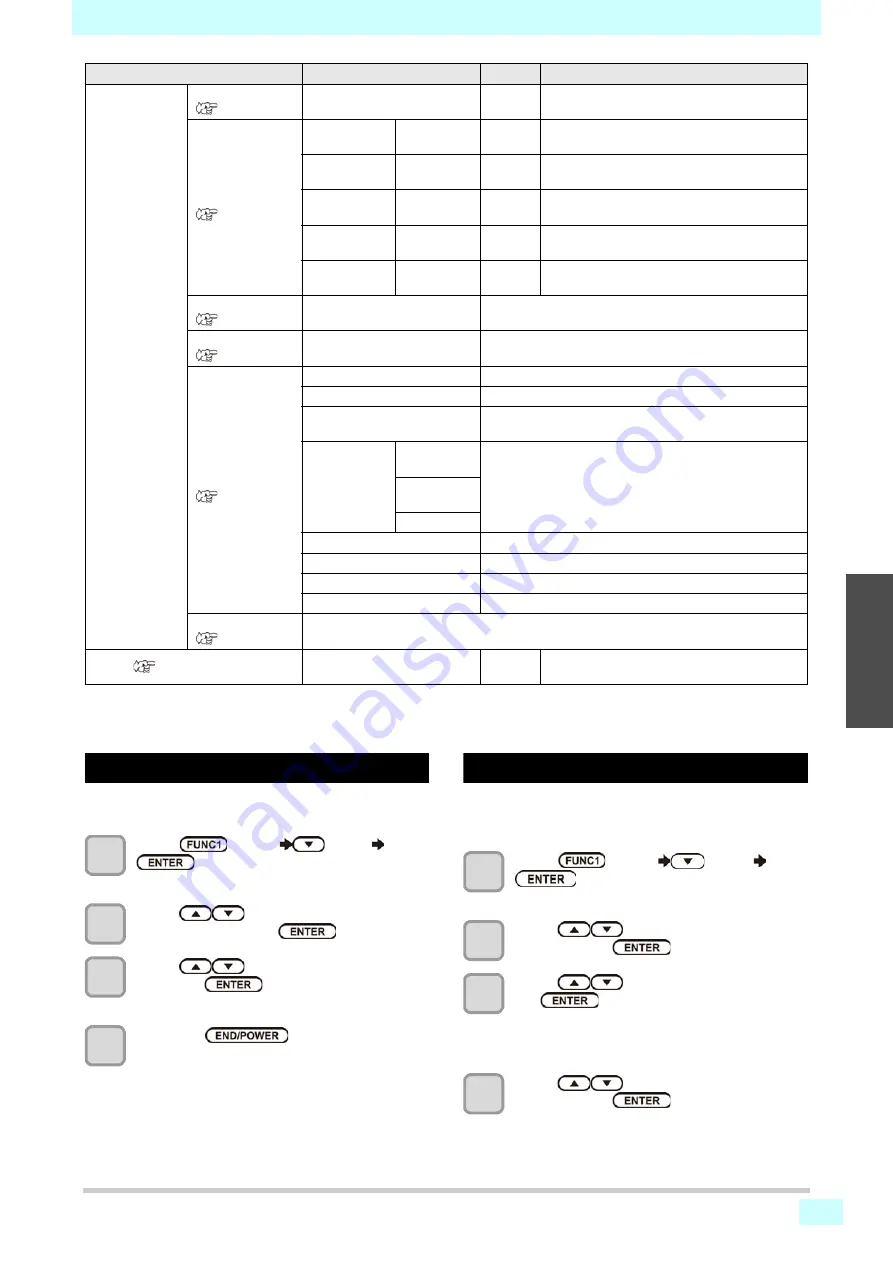
EVENT MAIL
Mail Delivery
(
ON / OFF
OFF
Set whether you send/ do not send the e-mail
when the set event occurs.
Select Event
(
Print Start
Event
ON / OFF
OFF
Set whether you send/ do not send the e-mail at
the start of printing.
Print End Event ON / OFF
OFF
Set whether you send/ do not send the e-mail at
the end of printing.
Error Event
ON / OFF
OFF
Set whether you send/ do not send the e-mail
when a error occurs.
Warning Event
ON / OFF
OFF
Set whether you send/ do not send the e-mail
when a warning occurs.
Other Event
ON / OFF
OFF
Set whether you send/ do not send the e-mail
when an event other than the above occurs.
Mail Address
(
Set the e-mail address to which
you send the event mail.
Alphanumeric characters and symbols (within 96
characters)
Message Subject
(
Set the characters to write in the
subject of the event mail.
Alphanumeric characters and symbols (within 8 characters)
Server Setup
(
SMTP Address
Set the SMTP server.
SMTP Port No.
Set the SMTP port number.
SENDER ADDRESS
Set the e-mail address to be used as the sender mail
address.
Authentication
POP before
SMTP
Set the SMTP server authentication method (SMTP
authentication).
SMTP
Authentication
OFF
User Name
*2
Set the user name used for the authentication.
Pass Word *2
Set the password used for the authentication.
POP3 Address
*3
Set the POP server.
APOP *3
Set ON/ OFF of APOP.
Transmit Test
(
Send the test e-mail.
RESET(
All setting values are returned to the status
default.
*1.
Settable when both of DHCP and AutoIP are [OFF]
*2.
Settable only when Auth. is not OFF
*3.
Settable only when Auth. is POP before SMTP
Function name
Set value
Default
Meaning
Summary of Contents for Tx300P-1800B
Page 12: ...xi Warning labels No Reorder Label 1 M910931 2 M907833 3 M903330 4 M907935 5 M913867 6 M913939...
Page 14: ...xiii Warning labels...
Page 60: ...2 30 Chapter 2 Basic Operation...
Page 120: ...Chapter 4 Maintenance 4 32...
Page 136: ...Chapter5 Troubleshooting 5 16...
Page 142: ...Chapter6 Appendix 6 6...