


PELLERIN MILNOR CORPORATION
1. At the MultiTrac or Drynet console, access the shuttle Encoder form:
a. In the Dryer/Shuttle Controller (DevComm Setup) window, select Configure, Shuttles
and Cobucs on the menu. This displays one or more tabbed forms—one for each shuttle
device in the system.
b. Select the tab corresponding to the shuttle with the new laser device. This displays the
main configuration form for this shuttle.
c. Near the bottom right of the form, find the field Shuttle has an Encoder. Select (or re-
select) the value 1. This displays the Configure Shuttle Encoder form (
Figure 7
).
2. Enter values in the fields on the left column of the encoder form in accordance with
Table 2
.
3. Do this procedure for each position at which the shuttle stops:
a. At the stationary shuttle control box, manually move the shuttle to the stop position.
Ensure that the shuttle is precisely aligned with the interfacing device.
b. At the laser device, read the distance value in hundredths of units (inches or millimeters
as previously configured). Hence, read the displayed value 26147 as 261 inches or
millimeters.
c. At the Drynet controller, enter this value (whole inches or millimeters) in the appropriate
field:
• Distance at Home Station
• Distance at Load Station ___
• Distance at Discharge Station ___
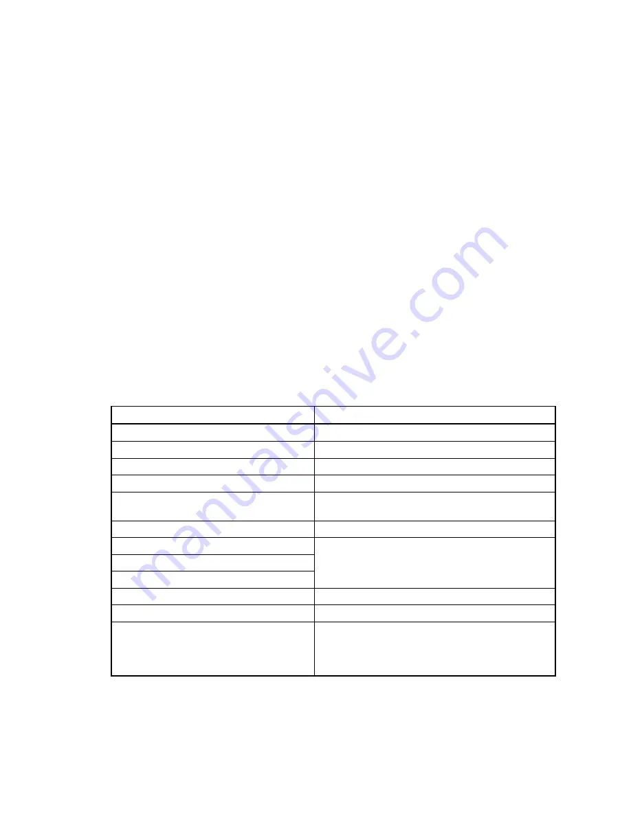
Table 2: Guidelines for Encoder Values for Laser Device
Data Field
Required Value or Guideline
Using laser tracking
1
Number of Load Stations
Per physical layout
Number of Discharge Stations
Per physical layout
Distance at Home Station
See
Item 3
below.
Slow Down Distance
Between 6 and 10 inches (152 and 254 mm)
recommended
High Speed Distance (feet)
Not currently implemented
Counts at Left Oops Target
Counts at Right Oops Target
Counts at Reset Point
Disabled and not applicable to laser device.
Stop Offset Counts
0
At Decel Time: in 10ths of a second
0
Laser Position
Face the direction that goods move as they are
loaded onto the shuttle bed. If the post-mounted
laser is located to the right of the shuttle, enter 0. If
to the left of the shuttle, enter 1.
4.
Testing
When you have entered all shuttle stop positions in the Drynet controller, test each position as
explained in document BIVSRC01 "How to Test Traversing Shuttle Stop Positions."
— End of BIVSVI01 —
40
Summary of Contents for COLFM 111
Page 2: ......
Page 4: ......
Page 5: ...Safety Information 1 1 ...
Page 22: ......
Page 23: ...Installation 2 19 ...
Page 48: ......
Page 49: ...Service and Maintenance 3 45 ...
Page 88: ......
Page 89: ...Dimensional Drawings 4 85 ...
Page 90: ......
Page 91: ...87 ...
Page 92: ...88 ...
Page 93: ...89 ...
Page 94: ......
Page 95: ...91 ...
Page 96: ......
Page 97: ...93 ...
Page 98: ...94 ...
Page 99: ...95 ...
Page 100: ...96 ...
Page 101: ...97 ...
Page 102: ...98 ...
Page 103: ...99 ...
Page 104: ...100 ...


