


OM-172 324 Page 4
2-3.
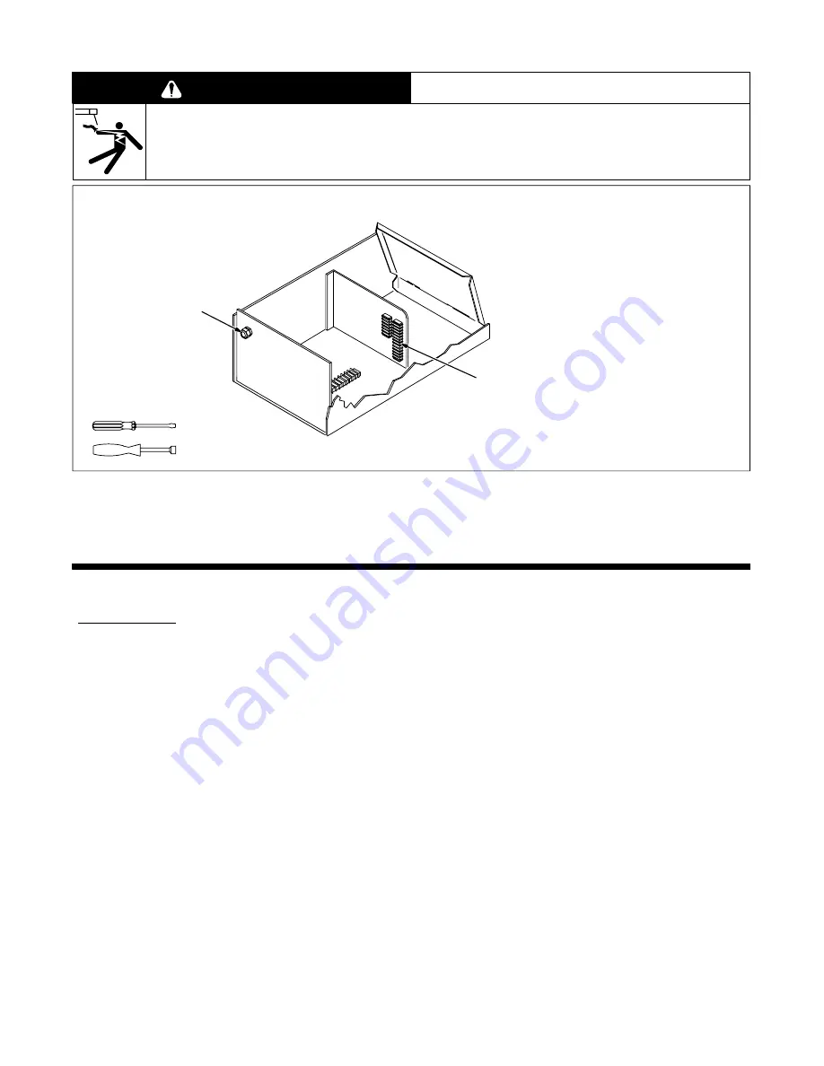
Connecting Optional Emergency Stop Push Button
WARNING
ELECTRIC SHOCK can kill.
•
Do not touch live electrical parts.
•
Turn Off robot, welding power source, and interface unit, and disconnect input power before inspecting or installing.
swarn1.1* 2/93
ST-801 146
Terminal strip 2T provides connec-
tion points for an optional normally
closed Emergency Stop (E-stop)
push button. To make connections,
proceed as follows.
Remove top cover.
1
Terminal Strip 2T
2
Strain Relief
Loosen strain relief and insert leads
from normally closed E-stop push
button. Route leads to 2T.
Remove jumper link across termi-
nals A and B on 2T. Keep for future
use.
Connect one lead from E-stop
switch to terminal A and the remain-
ing lead to terminal B.
Tighten strain relief and reinstall top
cover.
Tools Needed:
1/4 in
2
1
Figure 2-3. Connecting Optional Emergency Stop Push Button
SECTION 3 – OPERATIONAL TERMS
The following is a list of terms and their definitions as they apply to this interface unit:
General Terms:
Adaptive Pulse Welding
When the “adaptive pulse” welding process is selected, the unit will automati-
cally regulate pulse frequency in order to maintain a constant arc length, re-
gardless of change in welding wire stickout.
Abk (Background
Amperage)
Abk is the low weld current. Background current preheats welding wire and
maintains the arc. When background current is too low, the arc is unstable and
hard to maintain.
Apk (Peak Amperage)
Apk is the high pulse of welding current. Peak current melts the welding wire
and forms a droplet. The droplet is forced into the weld puddle.
Inductance
In short circuit GMAW welding, an increase in inductance will decrease the
number of short circuit metal transfers per second (provided no other changes
are made) and increase the arc-on time. The increased arc-on time makes the
pool more fluid.
PPS (Pulses Per Second)
PPS, pulse rate, and frequency (Hz) are used interchangeably. A PPS or pulse
rate of 60 Hz means 60 pulses of current are produced each second.
PWms (Pulse Width in
Milliseconds)
PWms is the time spent at peak current (1.2 ms is .0012 seconds). This time
must be long enough to form a droplet of welding wire. The stiffness or fluidity
of the molten weld puddle is controlled by PWms.
Synergic
Synergic refers to the unit’s ability to use preprogrammed pulse parameters to
determine the actual pulse settings of Peak Amperage, Background Amperage,
Pulse Frequency and Pulse Width at any specific wire feed speed setting.
Trim
Term used to represent arc length adjustments in pulse programs. Increasing
trim increases the actual arc length. Likewise, decreasing trim shortens arc
length. Trim is replaced by volts in MIG programs.
Summary of Contents for Robotic Interface II
Page 2: ......
Page 57: ...OM 172 324 Page 51 SD 171 360 A...
Page 58: ...OM 172 324 Page 52 Figure 12 2 Circuit Diagram For Microprocessor Board PC1...
Page 59: ...OM 172 324 Page 53 SD 161 039 A...
Page 60: ...OM 172 324 Page 54 Figure 12 3 Circuit Diagram For Motor Board PC3...
Page 61: ...OM 172 324 Page 55 SD 083 388 B...
Page 62: ...OM 172 324 Page 56 Figure 12 4 Circuit Diagram For Customer Interface Board PC4...
Page 63: ...OM 172 324 Page 57 SD 166 275...
Page 64: ...OM 172 324 Page 58 Figure 12 5 Circuit Diagram For Interface Board PC5...
Page 65: ...OM 172 324 Page 59 SD 165 466...
Page 66: ...OM 172 324 Page 60 Figure 12 6 Circuit Diagram For Filter Board PC6 SB 159 412...
Page 67: ...OM 172 324 Page 61 Figure 12 7 Circuit Diagram For Display Board PC7 SC 165 462 A...
Page 69: ...OM 172 324 Page 63 NOTES...
Page 78: ......


