background image

iSERIES Network Cameras · 

User Manual


1.


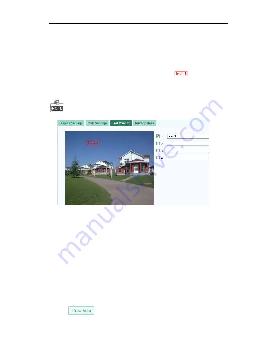
Enter the Text Overlay Settings interface: 

Configuration > Advanced Configuration > Image > Text Overlay 

2.


Check the checkbox in front of textbox to enable the on-screen display. 

3.


Input the characters in the textbox. 

4.


Use  the mouse to click and drag the red text frame 

  in the live view 

window to adjust the text overlay position.   

5.


Click 

Save


Up to 4 text overlays are configurable.


Figure 5-25


Text Overlay Settings 

5.5.4


Configuring Privacy Mask 

Purpose: 

Privacy mask enables you to cover certain areas on the live video to prevent certain 
spots in the surveillance area from being live viewed and recorded. 

Steps: 

1.


Enter the Privacy Mask Settings interface: 

Configuration > Advanced Configuration> Image > Privacy Mask 

2.


Check the checkbox of 

Enable Privacy Mask

 to enable this function. 

3.


Click

46 


Summary of Contents for A13B

Page 1: ...iSERIES Network Cameras User Manual V1 0 0 UD 7L0202D1364B01 1 ...

Page 2: ... or update the products or procedures described in the manual DISCLAIMER STATEMENT Underwriters Laboratories Inc UL has not tested the performance or reliability of the security or signaling aspects of this product UL has only tested for fire shock or casualty hazards as outlined in UL s Standard s for Safety UL60950 1 UL Certification does not cover the performance or reliability of the security ...

Page 3: ...nce received including interference that may cause undesired operation EU Conformity Statement This product and if applicable the supplied accessories too are marked with CE and comply therefore with the applicable harmonized European standards listed under the Low Voltage Directive 2006 95 EC the EMC Directive 2004 108 EC the RoHS Directive 2011 65 EU 2012 19 EU WEEE directive Products marked wit...

Page 4: ...ending on models according to the IEC60950 1 and Limited Power Source standard The power consumption cannot be less than the required value Do not connect several devices to one power adapter as an adapter overload may cause over heating and can be a fire hazard When the product is installed on a wall or ceiling the device should be firmly fixed To reduce the risk of fire or electrical shock do no...

Page 5: ...tion is required for a proper operating environment Keep the camera away from water and any liquid While shipping the camera should be packed in its original packing Improper use or replacement of the battery may result in hazard of explosion Please use the manufacturer recommended battery type For the camera supports IR you are required to pay attention to the following precautions to prevent IR ...

Page 6: ... and Capturing Pictures Manually 20 5 4 Operating PTZ Control 20 5 4 1 PTZ Control Panel 20 5 4 2 Setting Calling a Preset 21 Chapter 6 Network Camera Configuration 24 6 1 Configuring Local Parameters 24 6 2 Configuring Time Settings 25 6 3 Configuring Network Settings 27 6 3 1 Configuring TCP IP Settings 27 6 3 2 Configuring Port Settings 28 6 3 3 Configuring DDNS Settings 29 6 3 4 Configuring PP...

Page 7: ... 7 Storage Settings 56 7 1 Configuring NAS Settings 56 7 2 Configuring Recording Schedule 57 7 3 Configuring Snapshot Settings 60 Chapter 8 Playback 63 Chapter 9 Log Searching 65 Chapter 10 Others 67 10 1 Managing User Accounts 67 10 2 Configuring RTSP Authentication 69 10 3 Anonymous Visit 69 10 4 IP Address Filter 70 10 5 Viewing Device Information 72 10 6 Maintenance 73 10 6 1 Rebooting the Cam...

Page 8: ...bove version Vista Win7 Server 2003 Server 2008 32bits CPU Intel Pentium IV 3 0 GHz or higher RAM 1G or higher Display 1024 768 resolution or higher Web Browser Internet Explorer 6 0 and above version Apple Safari 5 02 and above version Mozilla Firefox 3 5 and above version and Google Chrome8 and above versions 7 ...

Page 9: ...a LAN you need to connect the network camera in the same subnet with your computer and install the MonitoringCenter software to search and change the IP of the network camera For the detailed introduction of MicroView MonitoringCenter please refer to Appendix 1 2 1 1 Wiring over the LAN The following figures show the two ways of cable connection of a network camera and a computer Purpose To test t...

Page 10: ...client software for detailed information 2 Change the IP address and subnet mask to the same subnet as that of your computer 3 Enter the IP address of network camera in the address field of the web browser to view the live video The default IP address is 192 0 0 64 and the port number is 8000 The default user name is admin and password is 12345 For accessing the network camera from different subne...

Page 11: ...ou start Please apply a static IP from an ISP Internet Service Provider With the static IP address you can connect the network camera via a router or connect it to the WAN directly Connecting the network camera via a router Steps 1 Connect the network camera to the router 2 Assign a LAN IP address the subnet mask and the gateway Refer to Section 2 1 2 Detecting and Changing the IP Address for deta...

Page 12: ... directly You can also save the static IP in the camera and directly connect it to the internet without using a router Refer to Section 2 1 2 Detecting and Changing the IP Address for detailed IP address configuration of the camera Figure 2 5 Accessing the Camera with Static IP Directly 2 2 2 Dynamic IP Connection Before you start Please apply a dynamic IP from an ISP With the dynamic IP address y...

Page 13: ...camera via a modem Purpose This camera supports the PPPoE auto dial up function The camera gets a public IP address by ADSL dial up after the camera is connected to a modem You need to configure the PPPoE parameters of the network camera Refer to Section 6 3 4 Configuring PPPoE Settings for detailed configuration Figure 2 6 Accessing the Camera with Dynamic IP The obtained IP address is dynamicall...

Page 14: ...S Settings for detailed configuration 3 Visit the camera via the applied domain name Private Domain Name Resolution Figure 2 8 Private Domain Name Resolution Steps 1 Install and run the IP Server software in a computer with a static IP 2 Access the network camera through the LAN with a web browser or the client software 3 Enable DDNS and select IP Server as the protocol type Refer to Section 6 3 3...

Page 15: ...left of the page 4 Input the user name and password and click Login The default user name is admin and the password is 12345 Multi language is supported English Simplified Chinese Traditional Chinese Russian Turkish Japanese Korean Thai Bulgarian Hungarian Czech Slovak French Italian German Spanish Portuguese Polish Greek Dutch etc Figure 3 1 Login Interface 5 Install the plug in before viewing th...

Page 16: ...iSERIES Network Cameras User Manual Figure 3 2 Download and Install Plug in Figure 3 3 Install Plug in 1 Figure 3 4 Install Plug in 2 15 ...

Page 17: ...Software The product CD contains the MonitoringCenter client software Client or PCNVR You can view the live video and manage the camera with the client software Follow the installation prompts to install the software The live view interface of MonitoringCenter is shown below Figure 3 5 MonitoringCenter Live View For detailed information about MonitoringCenter client software please refer to the us...

Page 18: ... with a mobile phone install the MonitoringCenter Mobile client software in your mobile phone You can download the software from iTunes App store or Google Play store For detailed information about MonitoringCenter Mobile client software please refer to the user manual of MonitoringCenter Mobile software 17 ...

Page 19: ...e live view page or you can click on the menu bar of the main page to enter the live view page Descriptions of the live view page Figure 4 1 Live View Page Menu Bar Click each tab to enter Live View Playback Log and Configuration interface Display Control Click each tab to adjust the layout and the stream type of the live view Live View Window Display the live view Toolbar Operations on the live v...

Page 20: ... toolbar to start the live view of the camera Figure 4 2 Live View Toolbar Table 4 1 Descriptions of the Toolbar Icon Description Start Stop live view Manually capture the pictures displayed in live view and then save it as a JPEG file or BMP file Manually start stop recording Audio on and adjust volume Mute Enable Disable two way audio Enable Disable e PTZ Before using the two way audio function ...

Page 21: ...ecord the live video The saving paths of the captured pictures and clips can be set on the Configuration Local Configuration page To configure remote scheduled recording please refer to Section 7 2 The captured image will be saved as JPEG or BMP file in your computer 4 4 Operating PTZ Control Purpose In the live view interface you can use the PTZ control buttons to realize pan tilt zoom control of...

Page 22: ...e mouse in the relative positions For the cameras which support lens movements only the direction buttons are invalid Table 4 2 Descriptions of PTZ Control Panel Button Description Zoom in out Focus near far Iris open close Light on off Wiper on off One touch focus Initialize lens 4 4 2 Setting Calling a Preset Setting a Preset 1 In the PTZ control panel select a preset number from the preset list...

Page 23: ...lens 3 Click to finish the setting of the current preset 4 You can click to delete the preset You can configure up to 128 presets Calling a Preset This feature enables the camera to point to a specified preset scene manually or when an event takes place For the defined preset you can call it at any time to the desired preset scene In the PTZ control panel select a defined preset from the list and ...

Page 24: ...iSERIES Network Cameras User Manual Figure 4 5 Calling a Preset 23 ...

Page 25: ...ser Steps 1 Enter the Local Configuration interface Configuration Local Configuration Figure 5 1 Local Configuration Interface 2 Configure the following settings Live View Parameters Set the protocol type and live view performance Protocol Type TCP UDP MULTICAST and HTTP are selectable TCP Ensures complete delivery of streaming data and better video quality yet the real time transmission will be a...

Page 26: ... to Set the saving path for the downloaded video files in playback mode Picture and Clip Settings Set the saving paths of the captured pictures and clipped video files Valid for the pictures you captured with the web browser Save snapshots in live view to Set the saving path of the manually captured pictures in live view mode Save snapshots when playback to Set the saving path of the captured pict...

Page 27: ...Server Address IP address of NTP server NTP Port Port of NTP server Interval The time interval between the two synchronizing actions with NTP server Figure 5 3 Time Sync by NTP Server If the camera is connected to a public network you should use a NTP server that has a time synchronization function such as the server at the National Time Center IP Address 210 72 145 44 If the camera is set in a cu...

Page 28: ...ync Manually Click tab to enable the DST function and Set the date of the DST period Figure 5 5 DST Settings 2 Click Save to save the settings 5 3 Configuring Network Settings 5 3 1 Configuring TCP IP Settings Purpose TCP IP settings must be properly configured before you operate the camera over network The camera supports both the IPv4 and IPv6 Both versions may be configured simultaneously witho...

Page 29: ...ault Gateway MTU settings and Multicast Address The valid value range of MTU is 500 1500 The Multicast sends a stream to the multicast group address and allows multiple clients to acquire the stream at the same time by requesting a copy from the multicast group address Before utilizing this function you have to enable the Multicast function of your router 3 Click Save to save the above settings A ...

Page 30: ...54 and it can be changed to any port No which is not occupied HTTPS Port The default port number is 443 and can be changed to any port No which is not occupied Server Port The default server port number is 8000 and it can be changed to any port No ranges from 2000 to 65535 3 Click Save to save the settings A reboot is required for the settings to take effect 5 3 3 Configuring DDNS Settings Purpose...

Page 31: ...e Three DDNS types are selectable NO IP IPServer and DynDNS DynDNS Steps 1 Enter Server Address of DynDNS e g members dyndns org 2 In the Domain text field enter the domain name obtained from the DynDNS website 3 Enter the Port of DynDNS server 4 Enter the User Name and Password registered on the DynDNS website 5 Click Save to save the settings Figure 5 9 DynDNS Settings IP Server 30 ...

Page 32: ...5 10 IPServer Settings For the US and Canada area you can enter 173 200 91 74 as the server address NO IP Steps 1 Enter Server Address of NO IP 2 In the Domain text field enter the domain name obtained from the NO IP website 3 Enter the Port of NO IP server 4 Enter the User Name and Password registered on the NO IP website 5 Click Save to save the settings A reboot is required for the settings to ...

Page 33: ... it is connected to the network Before you start Before setting the SNMP please download the SNMP software and manage to receive the camera information via SNMP port By setting the Trap Address the camera can send the alarm event and exception messages to the surveillance center The SNMP version you select should be the same as that of the SNMP software And you also need to use the different versi...

Page 34: ...on checkbox to enable the feature 3 Configure the SNMP settings The settings of the SNMP software should be the same as the settings you configure here 4 Click Save to save and finish the settings A reboot is required for the settings to take effect 5 3 6 Configuring 802 1X Settings Purpose 33 ...

Page 35: ...tion Advanced Configuration Network 802 1X Figure 5 13 802 1X Settings 2 Check the Enable IEEE 802 1X checkbox to enable the feature 3 Configure the 802 1X settings including EAPOL version user name and password The EAPOL version must be identical with that of the router or the switch 4 Enter the user name and password to access the server 5 Click Save to finish the settings A reboot is required f...

Page 36: ...CP refers to the Differentiated Service Code Point and the DSCP value is used in the IP header to indicate the priority of the data 3 Click Save to save the settings A reboot is required for the settings to take effect 5 3 8 Configuring FTP Settings Purpose You can configure the FTP server related information to enable the uploading of the captured pictures to the FTP server The captured pictures ...

Page 37: ...r Anonymous Access to the FTP Server in which case the user name and password won t be requested Check the checkbox to enable the anonymous access to the FTP server The anonymous access function must be supported by the FTP server 3 Click Save to save the settings If you want to upload the captured pictures to FTP server you have to enable the continuous snapshot or event triggered snapshot on Sna...

Page 38: ... Email notification to all designated receivers if an alarm event is detected e g motion detection event video loss video tampering etc Before you start Please configure the DNS Server settings under Basic Configuration Network TCP IP or Advanced Configuration Network TCP IP before using the Email function Steps 1 Enter the TCP IP Settings Configuration Basic Configuration Network TCP IP or Config...

Page 39: ...SMTP Port The SMTP port The default TCP IP port for SMTP is 25 not secured And the SSL SMTP port is 465 Enable SSL Check the checkbox to enable SSL if it is required by the SMTP server Attached Image Check the checkbox of Attached Image if you want to send emails with attached alarm images Interval The interval refers to the time between two actions of sending attached pictures Authentication opti...

Page 40: ...1Configuring NAT Network Address Translation Settings 1 Enter the NAT settings interface Configuration Advanced Configuration Network NAT 2 Choose the port mapping mode To port mapping with the default port number you can choose Port Mapping Mode as Auto To port mapping with the customized port numbers you can choose Port Mapping Mode as Manual And for manual port mapping you can customize the val...

Page 41: ...when the bandwidth is limited 3 You can customize the following parameters for the selected main stream or sub stream Video Type Select the stream type to video stream or video audio composite stream The audio signal will be recorded only when the Video Type is Video Audio Resolution Select the resolution of the video output Bitrate Type Select the bitrate type to constant or variable Video Qualit...

Page 42: ...e supported video encoding may differ according to the different platform I Frame Interval Set the I Frame interval to 1 400 SVC Scalable Video Coding is an extension of the H 264 AVC standard Set it OFF or ON according to your actual needs 4 Click Save to save the settings 5 4 2 Configuring Audio Settings Steps 1 Enter the Audio Settings interface Configuration Basic Configuration Video Audio Aud...

Page 43: ...era including image adjustment exposure settings day night switch backlight settings white balance image enhancement video adjustment etc The display parameters vary according to the different camera models Steps 1 Enter the Display Settings interface Configuration Basic Configuration Image Display Settings Or Configuration Advanced Configuration Image Display Settings 2 Set the image parameters o...

Page 44: ...y night switch you can choose the sensitivity of the switch as high normal and low Mirror The mirror function enables you to view another aspect of the image You can flip the image horizontally and vertically It can be used to view the image in the way you see it directly using your eyes WDR Wide dynamic range can be used when there is a high contrast of the bright area and the dark area of the sc...

Page 45: ...he grey scale as 0 255 or 16 235 Corridor mode To make a complete use of the 16 9 aspect ratio you can enable the corridor mode when you use the camera in a narrow view scene When installing turn the camera to the 90 degrees or rotate the 3 axis lens to 90 degrees and set the corridor mode as on you will get a normal view of the scene with 9 16 aspect ratio to ignore the needless information such ...

Page 46: ...ext field of Camera Name 4 Select from the drop down list to set the time format date format display mode and the OSD font size 5 You can use the mouse to click and drag the text frame in the live view window to adjust the OSD position Figure 5 24 Adjust OSD Location 6 Click Save to activate above settings 5 5 3 Configuring Text Overlay Settings You can customize the text overlay Steps 45 ...

Page 47: ...e view window to adjust the text overlay position 5 Click Save Up to 4 text overlays are configurable Figure 5 25 Text Overlay Settings 5 5 4 Configuring Privacy Mask Purpose Privacy mask enables you to cover certain areas on the live video to prevent certain spots in the surveillance area from being live viewed and recorded Steps 1 Enter the Privacy Mask Settings interface Configuration Advanced ...

Page 48: ...nfigure the network camera to respond to alarm events including motion detection video tampering alarm input alarm output and exception These events can trigger the alarm actions such as Notify Surveillance Center Send Email Trigger Alarm Output etc Check the checkbox of Notify Surveillance Center if you want to the alarm information pushed to your mobile phone as soon as the alarm is triggered 5 ...

Page 49: ...of Enable Motion Detection Figure 5 27 Enable Motion Detection 3 Click Click and drag the mouse on the live video image to draw a motion detection area You can draw up to 8 motion detection areas on the same image 4 Click to finish drawing 5 Optional Click to clear all of the areas 6 Optional Move the slider to set the sensitivity of the detection Tasks 2 Set the Arming Schedule for Motion Detecti...

Page 50: ...edule 2 Choose the day you want to set the arming schedule 3 Click to set the time period for the arming schedule 4 After you set the arming schedule you can copy the schedule to other days Optional 5 Click Save to save the settings The time of each period can t be overlapped Up to 8 periods can be configured for each day Figure 5 29 Arming Time Schedule 49 ...

Page 51: ...gger alarm output are selectable Optional Audible Warning Trigger the audible warning locally Notify Surveillance Center Send an exception or alarm signal to remote management software when an event occurs Send Email Send an email with alarm information to a user or users when an event occurs To send the Email when an event occurs you need to refer to Section 6 3 10 to set the related parameters U...

Page 52: ...o set the related parameters 5 6 2 Configuring Video Tampering Alarm Purpose You can configure the camera to trigger the alarm when the lens is covered and take alarm response action Steps 1 Enter the Video Tampering Settings interface Configuration Advanced Configuration Events Video Tampering Figure 5 31 Video Tampering Alarm 2 Check Enable Video Tampering checkbox to enable the video tampering ...

Page 53: ... 6 Click Save to save the settings 5 6 3 Configuring External Alarm Input Steps 1 Enter the Alarm Input Settings interface Configuration Advanced Configuration Events Alarm Input 2 Choose the alarm input No and the Alarm Type The alarm type can be NO Normally Open and NC Normally Closed Edit the name to set a name for the alarm input optional Figure 5 32 Alarm Input Settings 3 Click to set the arm...

Page 54: ...ced Configuration Events Alarm Output 2 Select one alarm output channel in the Alarm Output drop down list You can also set a name for the alarm output optional 3 The Delay time can be set to 5sec 10sec 30sec 1min 2min 5min 10min or Manual The delay time refers to the time duration that the alarm output remains in effect after alarm occurs 4 Click to enter the Edit Schedule Time interface The time...

Page 55: ...rror network disconnected IP address conflicted and illegal login to the cameras Steps 1 Enter the Exception Settings interface Configuration Advanced Configuration Events Exception 2 Check the checkbox to set the actions taken for the Exception alarm Refer to Task 3 Set the Alarm Actions Taken for Motion Detection in Section 6 6 1 54 ...

Page 56: ...rding to the steps in this chapter Steps 1 In the Other Alarm configuration interface check the checkbox of Enable PIR Alarm to activate the PIR alarm and define the alarm name in the Alarm Name field Figure 5 36 PIR Alarm Settings 2 Check the checkbox to select the linkage method taken for the PIR alarm Audible warning notify surveillance center send email upload to FTP trigger channel and trigge...

Page 57: ...rded files log files etc Steps 1 Add the network disk 1 Enter the NAS Network Attached Storage Settings interface Configuration Advanced Configuration Storage NAS Figure 6 1 Add Network Disk 2 Enter the IP address of the network disk and enter the default file Please refer to the User Manual of NAS for creating the file path 3 Click Save to add the network disk 2 Initialize the added network disk ...

Page 58: ...to the camera please refer to the steps of NAS disk initialization 6 2 Configuring Recording Schedule Purpose There are two kinds of recording for the cameras manual recording and scheduled recording For the manual recording refer to Section 5 3 Recording and Capturing Pictures Manually In this section you can follow the instructions to configure the scheduled recording By default the record files...

Page 59: ...ra starts to record at 9 59 55 The Pre record time can be configured as No Pre record 5 s 10 s 15 s 20 s 25 s 30 s or not limited Post record The time you set to stop recording after the scheduled time or the event For example if an alarm triggered recording ends at 11 00 and the post record time is set as 5 seconds the camera records until 11 00 05 The Post record time can be configured as 5 s 10...

Page 60: ...kbox Set the Start Time and End Time The time of each segment can t be overlapped Up to 4 segments can be configured 2 Select a Record Type The record type can be Normal Motion Detection Alarm Motion Alarm Motion Alarm PIR Alarm Wireless Alarm Emergency Alarm or Motion Alarm Input PIR Wireless Emergency Normal If you select Normal the video will be recorded automatically according to the time of t...

Page 61: ...me time Besides configuring the recording schedule you have to configure the settings on the Motion Detection and Alarm Input Settings interfaces Please refer to Section 6 6 1 and Section 6 6 3 for detailed information Record Triggered by Motion Alarm If you select Motion Alarm the video will be recorded when the external alarm is triggered or the motion is detected Besides configuring the recordi...

Page 62: ...ons to upload the snapshots to FTP Upload continuous snapshots to FTP Steps 1 Configure the FTP settings and check Upload Picture checkbox in FTP Settings interface Please refer to Section 6 3 8 Configuring FTP Settings for more details to configure FTP parameters 2 Check the Enable Timing Snapshot checkbox Upload event triggered snapshots to FTP Steps 1 Configure the FTP settings and check Upload...

Page 63: ...iSERIES Network Cameras User Manual Figure 6 7 Snapshot Settings 62 ...

Page 64: ...ins how to view the remotely recorded video files stored in the network disks or SD cards Steps 1 Click on the menu bar to enter playback interface Figure 7 1 Playback Interface 2 Select the date and click Figure 7 2 Search Video 3 Click to play the video files found on this date 63 ...

Page 65: ... by frame Enable Disable digital zoom You can choose the file paths locally for downloaded playback video files and pictures in Local Configuration interface Please refer to Section 6 1 for details Drag the progress bar with the mouse to locate the exact playback point You can also input the time and click to locate the playback point in the Set playback time field You can also click to zoom out i...

Page 66: ...ore you start Please configure network storage for the camera or insert a SD card in the camera Steps 1 Click tab on the menu bar to enter log search interface Figure 8 1 Log Search Interface 2 Set the log search conditions to specify the search including the Major Type Minor Type Start Time and End Time Figure 8 2 Log Search 3 Click to search log files The matched log files will be displayed as f...

Page 67: ...iSERIES Network Cameras User Manual Figure 8 3 Log Results 4 To export the log files click to save the log files in your computer or into the external storage device 66 ...

Page 68: ...modify or delete other accounts Up to 15 user accounts can be created Figure 9 1 User Information Add a User Steps 1 Click to add a user 2 Input the new User Name select Level and input Password The level indicates the permissions you give to the user You can define the user as Operator or User 3 In the Basic Permission field and Camera Configuration field you can check or uncheck the permissions ...

Page 69: ...eps 1 Left click to select the user from the list and click 2 Modify the User Name Level or Password 3 In the Basic Permission field and Camera Configuration field you can check or uncheck the permissions 4 Click OK to finish the user modification Figure 9 3 Modify a User 68 ...

Page 70: ...rity RTSP Authentication Figure 9 4 RTSP Authentication 2 Select the Authentication type basic or disable in the drop down list to enable or disable the RTSP authentication If you disable the RTSP authentication anyone can access the video stream by the RTSP protocol via the IP address 3 Click Save to save the settings 9 3 Anonymous Visit Purpose Enabling this function allows visit for whom doesn ...

Page 71: ...mous by the next time you logging in Figure 9 6 Login Interface with an Anonymous Checkbox 4 Check the checkbox of Anonymous and click Login The anonymous user only has the permissions to get the live view and do the quick operations on the live view page 9 4 IP Address Filter Purpose This function makes it possible for access control Steps 1 Enter the IP Address Filter interface Configuration Adv...

Page 72: ...dress Filter in the drop down list Forbidden and Allowed are selectable 4 Set the IP Address Filter list Add an IP Address Steps 1 Click to add an IP 2 Input the IP Adreess Figure 9 8 Add an IP 3 Click to finish adding Modify an IP Address Steps 1 Left click an IP address from filter list and click button 2 Modigy the IP address in the text filed 71 ...

Page 73: ...rface Configuration Basic Configuration System Device Information Or Configuration Advanced Configuration System Device Information In the Device Information interface you can edit the Device Name Other information of the network camera such as Model Serial No Firmware Version Encoding Version Number of Channels Number of HDDs Number of Alarm Input and Number of Alarm Output are displayed The info...

Page 74: ...re 9 11 Reboot the Device 9 6 2 Restoring Default Settings Steps 1 Enter the Maintenance interface Configuration Basic Configuration System Maintenance Or Configuration Advanced Configuration System Maintenance 2 Click or to restore the default settings Figure 9 12 Restore Default Settings After restoring the default settings the IP address is also restored to the default IP address please be care...

Page 75: ...the camera after importing configuration file 9 6 4 Upgrading the System Steps 1 Enter the Maintenance interface Configuration Basic Configuration System Maintenance Or Configuration Advanced Configuration System Maintenance 2 Click to select the local upgrade file and then click to start remote upgrade The upgrading process will take 1 to 10 minutes Please don t disconnect power of the camera dur...

Page 76: ...of the camera Transparent Channel Connect a serial device directly to the camera The serial device will be controlled remotely by the computer through the network Steps 1 Enter RS 232 Port Setting interface Configuration Advanced Configuration System RS232 Figure 9 14 RS 232 Settings If you want to connect the camera by the RS 232 port the parameters of the RS 232 should be exactly the same with t...

Page 77: ...launch MonitoringCenter software it automatically searches the online devices every 15 seconds from the subnet where your computer locates It displays the total number and information of the searched devices in the Online Devices interface Go to Device Management and click Server tab on the left top of the window and you can see the online devices listed on the right bottom of the window Figure A ...

Page 78: ... Enter the admin password in the Manager Password field and click to save the changes Figure A 1 2 Modify Network Parameters Restore default password Steps 1 Select the device you want to restore the default password 2 Click 3 Input the security code got from the technical support from our company 4 Click to restore the default password 77 ...

Page 79: ...Set the LAN parameters of the router as in the following figure including IP address and subnet mask settings Figure A 2 2 Set the LAN parameters 3 Set the port mapping in the virtual severs of Forwarding By default camera uses port 80 8000 554 and 8200 You can change these ports value with web browser or client software Example When the cameras are connected to the same router you can configure t...

Page 80: ...d to 8205 Steps 1 As the settings mentioned above map the port 80 8000 554 and 8200 for the network camera at 192 168 1 23 2 Map the port 81 8001 555 and 8201 for the network camera at 192 168 1 24 3 Enable ALL or TCP protocols 4 Check the Enable checkbox and click Figure A 2 3 Port Mapping The port of the network camera cannot conflict with other ports For example some web management port of the ...

Page 81: ......

Reviews: