The following step is only necessary, if you also want to complete a zero point adjustment.
8. Analyse the sensor values determined during setup mode. If the displayed values do not match the
ones of the reference measurement, the zero point will need to be adjusted. To do so, calculate the
difference between the determined sensor values and the reference measurement and enter the
difference in the input field for the "Trimming" parameter (see "Measurement channels" on page 83).
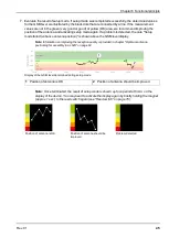
As the "Trimming" parameter is added to the measurement value of the sensor, a negative prefix must
be set for the "Trimming" parameter if the determined value is greater than the reference measurement
(see "Additional explanation on the zero point adjustment and installation height of the pressure
sensor" on page 84).
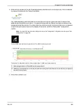
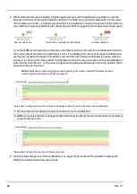
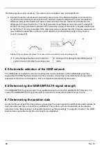
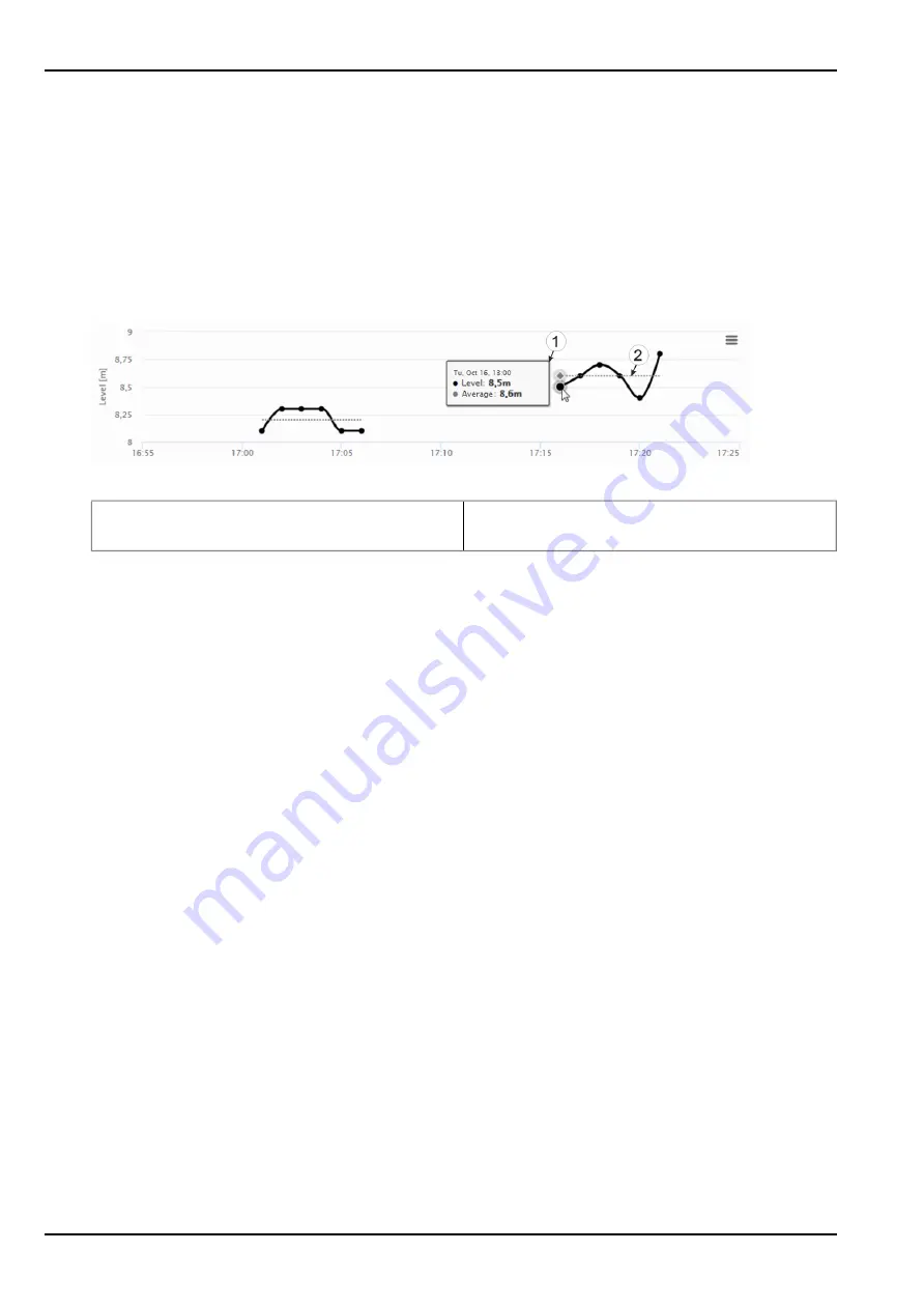
Display of the measurement values for a sensor which were determined during setup mode
1
Tool tip that specifies the sensor value at a
certain time and indicates the average value
2
Average of the data generated during setup
mode.
6.5 Automatic selection of the GSM network
The GSM network to which the device should register must be selected, as the myDatalogGauge 3G is
equipped with a SIM chip that provides a mobile connection via a variety of international service providers
(see www.microtronics.com/footprint ). This is completed automatically by the device.
6.6 Determining the GSM/UMTS/LTE signal strength
The GSM/UMTS/LTE signal strength is only updated during the connection establishment. However, the
value of the GSM/UMTS/LTE signal strength is copied in the measurement data for every record.
6.7 Determining the position data
An internal flag is set each time the position cycle expires thus ensuring that the GSM position data will also be
determined the next time a connection is established. The position cycle can be selected via the relevant
parameter in the "Basic settings" configuration section (see "Basic settings" on page 92). If set to 0, the GSM
position data is generated every time a connection is established.
46
Rev. 01
Summary of Contents for myDatalogGauge 3G
Page 2: ......
Page 10: ...2 2 BLE Gauge 10 Rev 01 ...
Page 11: ...Chapter 2 Declaration of conformity Rev 01 11 ...
Page 12: ......
Page 13: ...Chapter 3 Ex certification Chapter 3 Ex certification 3 1 BLE 3G Gateway ATEX Rev 01 13 ...
Page 14: ...14 Rev 01 ...
Page 15: ...Chapter 3 Ex certification Rev 01 15 ...
Page 16: ...16 Rev 01 ...
Page 17: ...Chapter 3 Ex certification 3 2 BLE Gauge Rev 01 17 ...
Page 18: ...18 Rev 01 ...
Page 19: ...Chapter 3 Ex certification Rev 01 19 ...
Page 20: ...20 Rev 01 ...
Page 134: ......
Page 140: ......
Page 152: ......
Page 154: ......


