


2.
Ensure access to the back of the unit is possible to wire up the device.
3.
Fix the unit to the rack using four #10-32 (M6) screws.
Note:
Rack mounting screws are not provided.
Note:
The device will heat up and cause the surrounding devices to heat up as well. Forced air flow is not required
for the unit to operate throughout its rated temperature range. However, any reduction in temperature will improve the
long-term reliability of all the equipment in the rack space.
6.5
Making Ground and Power Connections
This section describes how to establish safe ground and power connections to each of the GridTime 3000’s ports.
6.5.1
Ground Connections
This section describes how to establish safe grounding connections to the GridTime 3000.
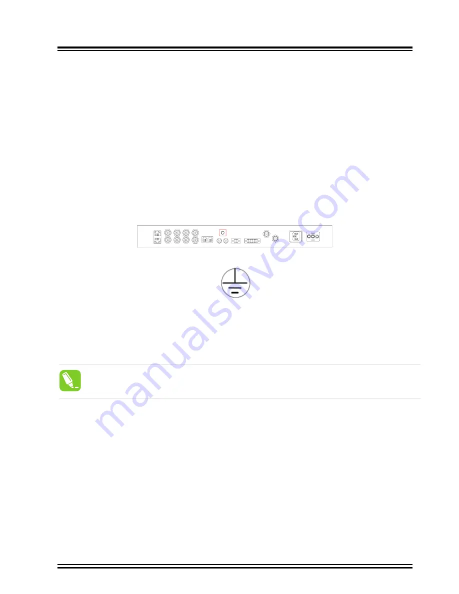
Frame ground connections are made using the M4 Grounding Terminal Studs, which are marked with the universal
ground symbol, as shown in
. These studs are located in the middle of the back panel
(above the ST Fiber ports) for the GridTime 3000
GridTime 3000 Ground connection
Figure 6-4. GridTime 3000 Ground Connection
Figure 6-5. Universal Ground Symbol
After installing the GridTime 3000 into the rack, connect the chassis to the proper grounding zone or master ground
bar per local building codes for grounding.
Run a 16 AWG (1.5 mm²) green/yellow-striped insulated wire from the GridTime 3000 grounding lug to the earth
ground on the rack. All bare grounding connection points to the GridTime 3000 shall be cleaned and coated with an
anti-oxidant solution before connections are made.
Tip:
Recommendation
: Although there are a number of methods for connecting the equipment to earth
ground, Microchip recommends running a cable of the shortest possible length from the ground lug to
earth ground
1.
Crimp the customer-supplied UL listed 18 AWG Ring Lug to one end of the 16 AWG wire. Connect the ring lug
to the ground terminal on the left side of the front panel using the supplied M4 Kept machine nut, tightening
to a torque value of 30 in-lbs, (3,4 Nm ). The surface of the GridTime 3000 earth grounding terminal must be
clean of contaminants and oxidation.
2.
Crimp the appropriate customer-supplied UL listed 18 AWG Ring Lug to the other end of the 1.5 mm² /
16 AWG green/yellow-striped wire. Remove the paint and sand the area around the screw hole to ensure
the proper conductivity. Coat the connection with an electrically conductive antioxidant compound such as
Kopr-shield spray. Connect this Ring Lug to the rack with appropriate customer supplied screws and external
star lock washers, tightening to a torque value of 53.45 in-lbs, (6 Nm ).
3.
Using a digital voltmeter, measure between the ground and chassis and verify the resistance between them.
Installation
©
2022 Microchip Technology Inc.
and its subsidiaries
Manual
DS00004572A-page 31


