Page
40
of
64
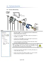
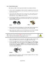
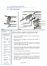
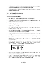
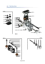
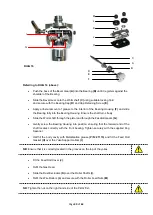
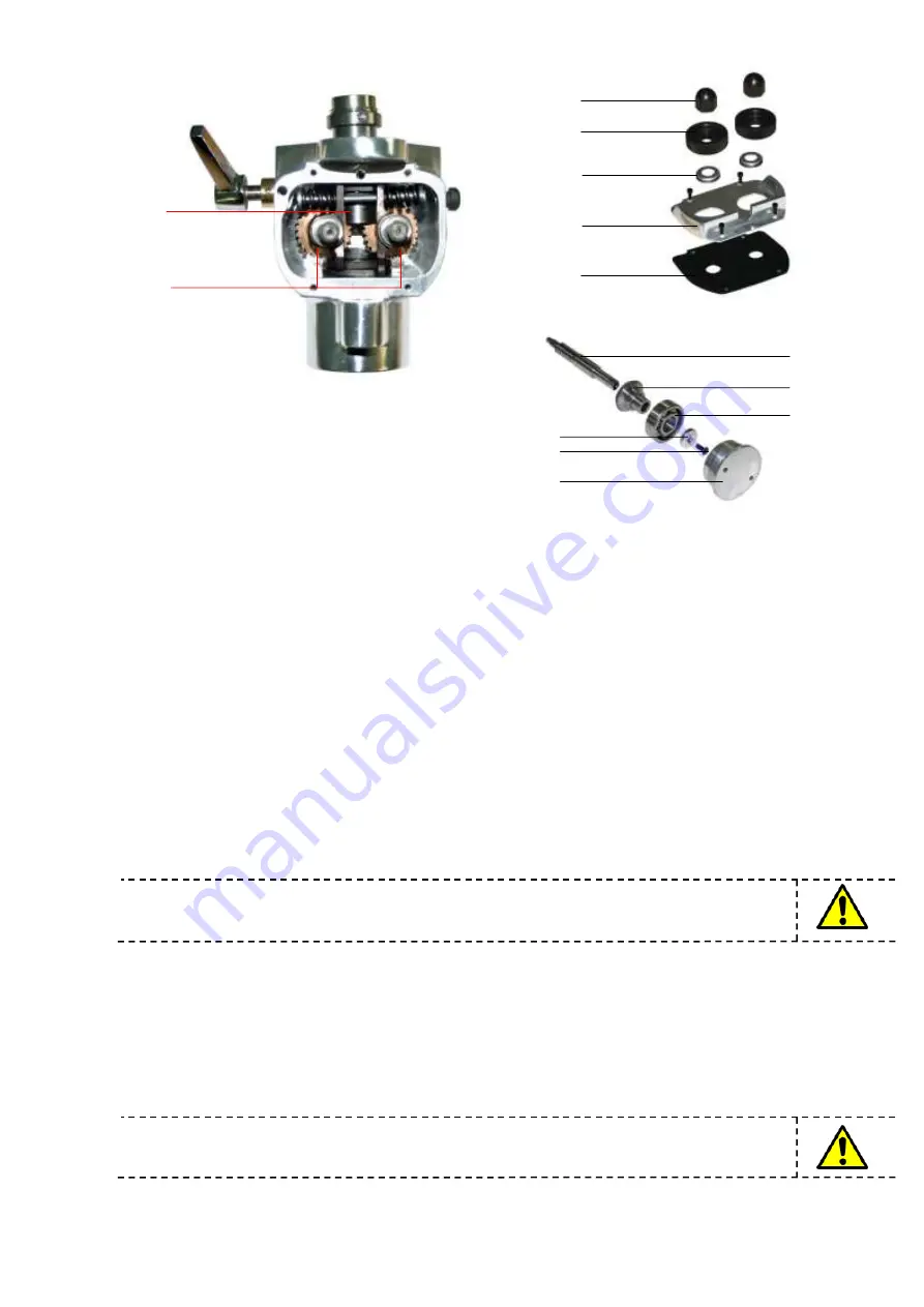
Referring to DIAG 16 (above):
Push the boss of the Bevel Gear
(A)
into the Bearing
(B)
until it registers against the
shoulder of the Bearing.
Slide the Bevel Gear onto the Wormshaft
(C)
using suitable locking fluid
and secure with the Bearing Cap
(D)
and Cap Retaining Screw
(E)
.
Apply a liberal amount of grease to the interior of the Bearing Housing
(F)
and slide
the Bearing fully into the Bearing Housing. Ensure the shaft turns freely
Slide the Wormshaft through the pistol and through the Feedroll Gears
(G)
.
Gently screw the Bearing Housing into position, ensuring that the forward end of the
shaft locates correctly with the front bearing. Tighten securely with the supplied Peg
Spanner.
Half fill the body cavity with Metallisation grease
(P/N: 21173)
and fit the Feed Roll
Gasket
(H)
over the Yoke Support collars
(I)
.
NB
: Ensure that it is correctly located in the grooves on the top of the yokes
Fit the Feed Roll Cover
(J)
.
Refit the Gas Head.
Slide the Dust Excluders
(K)
over the Roller Shafts
(I)
.
Refit the Wire Rollers
(L)
and secure with the Roller Feed Nuts
(M)
.
NB
: Tighten the nut on the right hand side of the Pistol first.
DIAG 16
G
I
H
J
K
L
M
A
B
C
D
E
F
Summary of Contents for MK 73
Page 1: ...Page 1 of 64 ssue 21 11 11 ...
Page 43: ...Page 43 of 64 SECTION 5 FAULT FINDING 5 1 Troubleshooting 5 1 2 Flowmeter Troubleshooting ...
Page 58: ...Page 58 of 64 SECTION 8 INFORMATION TABLES 8 1 Flowmeter Settings 8 2 Nozzle Selection Chart ...
Page 61: ...Page 61 of 64 Notes ...
Page 62: ...Page 62 of 64 ...
Page 63: ...Page 63 of 64 ...

