Page
39
of
64
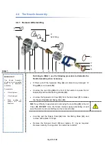
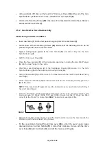
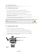
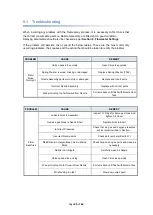
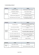
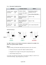
Register the Socket Set Screws
(E)
with the shaft dimples and tighten to hold the shafts
steady. Check for free rotation. It is recommended that locking fluid is used on these screws.
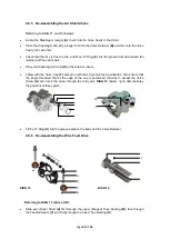
Fit the inner to the outer Yoke Assembly.
Place in the Pistol Body, making sure that the tension lugs are located towards the front of the
pistol.
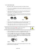
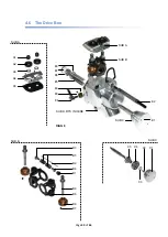
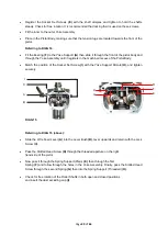
Referring to DIAG 14:
Fit the Bearing
(F)
to the Yoke Support
(G)
then slide it through the front of the pistol body and
through the Yoke Assembly until it registers in the machined recess of the Pistol Body.
Match the position of the Socket Set Screw
(I)
with the Yoke Support Dimple
(H)
, and tighten
securely.
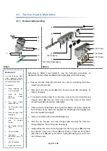
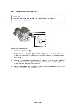
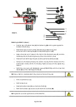
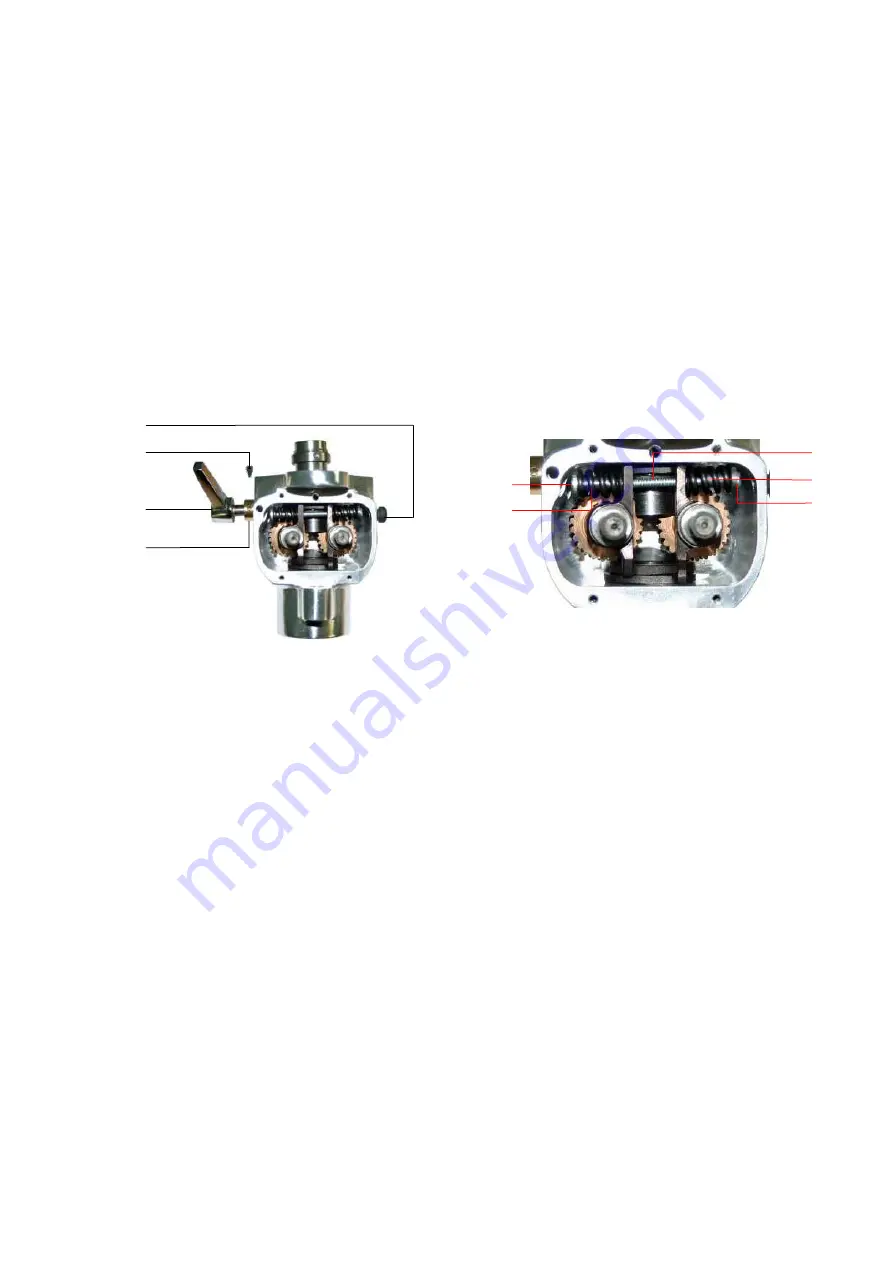
Referring to DIAG 15 (above):
Slide the Wire Feed Lever
(A)
into the Lever Bush
(B)
, lever upwards and retain with the Lock
Screw
(C)
.
Pass the Slotted Head Screw
(D)
through the threaded aperture on the right
hand side of the pistol.
Now pass it through the Spring Support (Plain)
(E)
, then through the first
Spring
(F)
and follow through the holes in the Yoke Assembly. Finally, pass the Slotted Head
Screw through the second Spring
(G)
then into the Spring Support (Threaded)
(H)
.
Check for free rotation of the Roller Shafts in both open and closed positions
and insert the dust excluding cap
(I)
.
DIAG 15
D
E
F
G
H
A
B
C
I
Summary of Contents for MK 73
Page 1: ...Page 1 of 64 ssue 21 11 11 ...
Page 43: ...Page 43 of 64 SECTION 5 FAULT FINDING 5 1 Troubleshooting 5 1 2 Flowmeter Troubleshooting ...
Page 58: ...Page 58 of 64 SECTION 8 INFORMATION TABLES 8 1 Flowmeter Settings 8 2 Nozzle Selection Chart ...
Page 61: ...Page 61 of 64 Notes ...
Page 62: ...Page 62 of 64 ...
Page 63: ...Page 63 of 64 ...

