Page
35
of
64
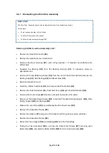
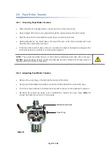
4.6.1 Dismantling the Wire Drive Assembly
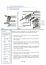
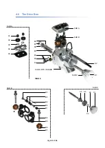
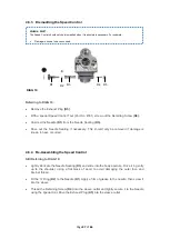
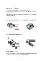
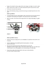
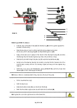
Referring to DIAG 8
and Sub Assembly’s A-C:
Remove the Rear Wire Guide
(E2)
.
Remove the Gas Head, as in Section 4.4.
Unscrew the Bear Housing
(E1)
with a Peg Spanner / C Spanner and withdraw the
Wormshaft.
Separate the Bearing
(C4)
from the Bearing Housing
(C1)
, if necessary using an
appropriate tool.
Unscrew the Cap Retaining Screw
(C2)
from the end of the Wormshaft and remove the
Bearing Cap
(C3)
, Ball Bearing
(C4)
and Bevel Gear
(C5)
.
Examine all parts for wear.
Undo the 2 Roller Feed Nuts
(A1)
and remove the Wire Rollers
(A2)
.
Remove the Dust Excluders
(A3)
, Feed Roll Cover
(A4)
and Feed Roll Gasket
(A5)
.
Unscrew the Cover Screw
(B1)
found on the right hand side of the pistol.
Screw out the Slotted Head Screw
(B2)
, retain the Threaded Spring Support
(B4)
, Plain
Spring Support
(B3)
and Springs
(B5)
.
Slacken the Lock Screw
(E3)
and withdraw the Wire Feed Lever
(E4)
.
Remove the Socket Set Screw
(E9)
.
Remove the Spacer
(E7)
using one of the Gas Head Fixing Screws as an extractor.
Remove the Socket Set Screw
(E8)
.
Extract the Yoke Support
(E5)
and Bearing
(E6)
from the Pistol Body.
Taking the Yoke Assembly
(B6)
, unscrew the Socket Set Screws
(B7)
securing each
Roller Gear
(B8)
, and slide the Roller Shafts
(B9)
from the Yoke Assembly
(B6)
.
WHEN & WHY?
The Wire Drive Assembly should only be dismantled when it is absolutely necessary.
For example:
There is excessive play in Wire Rollers.
The Wire Rollers cannot be opened.
The Wire Feed Lever spins through 360°
Summary of Contents for MK 73
Page 1: ...Page 1 of 64 ssue 21 11 11 ...
Page 43: ...Page 43 of 64 SECTION 5 FAULT FINDING 5 1 Troubleshooting 5 1 2 Flowmeter Troubleshooting ...
Page 58: ...Page 58 of 64 SECTION 8 INFORMATION TABLES 8 1 Flowmeter Settings 8 2 Nozzle Selection Chart ...
Page 61: ...Page 61 of 64 Notes ...
Page 62: ...Page 62 of 64 ...
Page 63: ...Page 63 of 64 ...

