Page
38
of
64
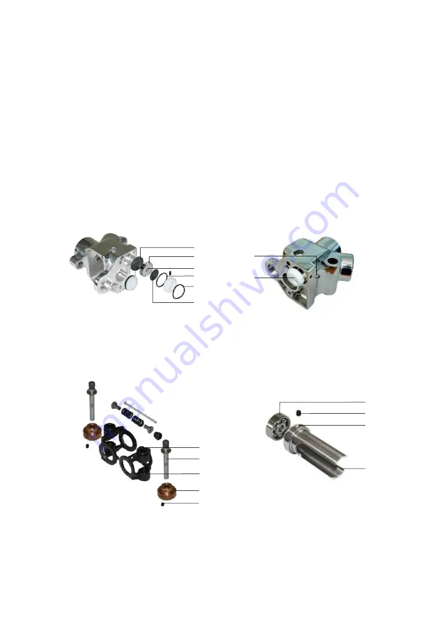
4.6.5 Re-Assembling the Air Shield Valve
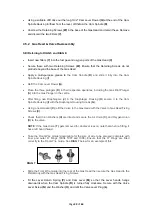
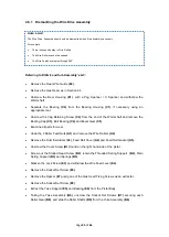
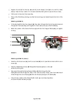
Referring to DIAG 11 and 12 (below):
Locate the Diaphragm (Large)
(A)
. Insert into the Valve Cavity in the Pistol.
Place the Diaphragm Disc
(C)
, plunger first into the Valve Retainer
(B)
and then into the Valve
Cavity, disc side first.
Check that the disc is free to slide, and fit an ‘O’ Ring
(E)
into the groove formed between the
retainer and the cavity wall.
Place the Diaphragm (Small)
(D)
in the retainer recess.
Follow with the Valve Cap
(F)
, placed in with the single hole facing outwards. Also ensure that
the single threaded hole at the edge of the cap is positioned correctly to accept the Valve
Screw
(G)
and insert the screw through the body wall.
DIAG 12
(below, right) demonstrates
the positions of these parts.
Fit the ‘O’ Ring
(H)
into the groove between the body and the Valve Retainer.
4.5.6 Re-Assembling the Wire Feed Drive
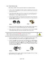
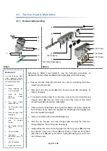
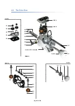
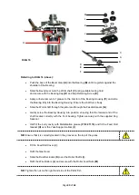
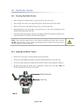
Referring to DIAG 13 (above, left):
Slide each Roller Shaft
(A)
first through the upper (flanged) Yoke Bearing
(B)
, then through
the Feedroll Gears
(C)
and finally though the lower Yoke Bearing
(D)
.
G
F
A
C
D
E
DIAG 13
DIAG 14
I
Summary of Contents for MK 73
Page 1: ...Page 1 of 64 ssue 21 11 11 ...
Page 43: ...Page 43 of 64 SECTION 5 FAULT FINDING 5 1 Troubleshooting 5 1 2 Flowmeter Troubleshooting ...
Page 58: ...Page 58 of 64 SECTION 8 INFORMATION TABLES 8 1 Flowmeter Settings 8 2 Nozzle Selection Chart ...
Page 61: ...Page 61 of 64 Notes ...
Page 62: ...Page 62 of 64 ...
Page 63: ...Page 63 of 64 ...

