


FOCKE MELER GLUING SOLUTIONS
5-4
MAINTENANCE
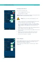
4. Replace the joints if they are damaged.
5. Unscrew the old cartridge in the clockwise direction. Screw the
assembly up again, counterclockwise.
6. Put the assembly back inside the distributor and tighten the screws.
7. Continue to work as normal.
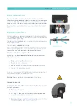
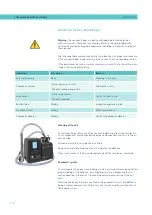
Changing the inlet filter
Warning:
It is important to install and remove the filter as instructed below, to
prevent the inlet valve from coming loose.
Bear in mind that the inlet filter is screwed onto the inlet valve via a right-
handed thread and that this, in turn, is screwed onto the distributor’s adapter
via a left-handed thread.
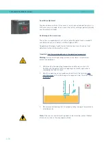
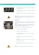
1. Empty the tank.
2. Remove the grid from the bottom of the tank, taking care not to scratch
it.
3. Put the unit on Standby.
4. Remove the filter unit with a size 17 socket driver, turning the unit’s
head anticlockwise.
5. Depending on how dirty the filter is, replace the mesh or the entire
unit, disposing of it in accordance with the current waste regulations.
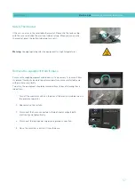
6. Reinstall the filter unit, screwing it clockwise onto the inlet valve.
Important:
It should only be tightened by hand and should not be forced, to
avoid loosening the inlet valve.
7. Fill the tank with adhesive and continue working as normal.
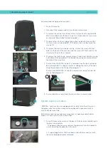
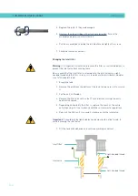
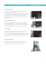
Inlet valve
Right-handed thread
Left-handed thread
Inlet filter
Summary of Contents for Micron + 10
Page 10: ...FOCKE MELER GLUING SOLUTIONS TABLE OF CONTENTS This page is intentionally left blank ...
Page 38: ...FOCKE MELER GLUING SOLUTIONS INSTALLATION 3 16 This page is intentionally left blank ...
Page 74: ...FOCKE MELER GLUING SOLUTIONS 4 36 MELTER OPERATION This page is intentionally left blank ...
Page 84: ...FOCKE MELER GLUING SOLUTIONS 5 10 MAINTENANCE This page is intentionally left blank ...
Page 91: ...MA 5162 ENG MICRON PISTON ADHESIVE MELTER ELECTRICAL DRAWINGS 7 1 7 ELECTRICAL DRAWINGS ...
Page 92: ...FOCKE MELER GLUING SOLUTIONS 7 2 ELECTRICAL DRAWINGS This page is intentionally left blank ...
Page 102: ...FOCKE MELER GLUING SOLUTIONS 8 10 PNEUMATIC DIAGRAM This page is intentionally left blank ...
Page 104: ...FOCKE MELER GLUING SOLUTIONS 9 2 SPARE PARTS LIST This page is intentionally left blank ...