


FOCKE MELER GLUING SOLUTIONS
INSTALLATION
3-2
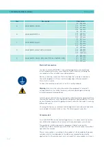
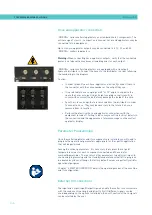
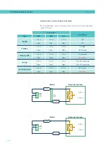
Electrical Consumption
In order to install a ‘’ series melter/applicator, we should take
into consideration the total consumption of the installation, including the
consumption of the installed hoses and applicators.
Before connecting, make sure that the voltage that is being connected to
the melter/applicator is the correct one appearing on the equipment’s
characteristics plate.
Connect the machine and check to see if it is well grounded.
Warning:
Risk of electrocution. Even when the equipment is turned off,
voltage remains in the intake terminals, which may be dangerous during
internal equipment manipulations.
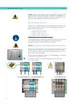
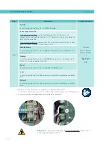
Install a power switch for disconnecting the melter/applicator equipment from
the electrical network. It must be protected against overload and short circuits
by circuit breaker and install appropriate personal protection leads to mass by
differential switch.
Consumption figures, according to melter/applicator and output configuration,
are included in the table in the section ‘Electrical power connection’.
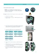
Compressed air
To install ‘’ series melters/applicators, it is necessary to have a dry,
non-lubricated compressed air system with a maximum pressure of 6 bar.
The applicator’s internal pneumatic equipment is able to work with a
minimum of 0.5 bar, however, pressure lower than this will cause intermittent
operational anomalies.
The air consumption is according to the number of stroke made by the pump
cylinder, which in turn depends on the adhesive consumption during the
application. It is therefore necessary to estimate this consumption in all cases.
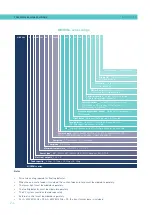
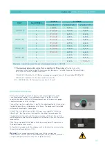
Item
Description
Dimension
A
EQUIPMENT LENGTH
5 l 588 mm
10 l 671 mm
20 l 671 mm
35 l 742 mm
B
EQUIPMENT WIDTH
5 l 339 mm
10 l 339 mm
20 l 383 mm
35 l 435 mm
C
EQUIPMENT HEIGHT
5 l 481 mm
10 l 481 mm
20 l 526 mm
35 l 673 mm
D
EQUIPMENT HEIGHT WITH LID OPEN
5 l 628 mm
10 l 760 mm
20 l 875 mm
35 l 1067 mm
E
EQUIPMENT LENGTH WITH ELECTRICAL CABINET OPEN
5 l 838 mm
10 l 921 mm
20 l 921 mm
35 l 992 mm
Summary of Contents for Micron + 10
Page 10: ...FOCKE MELER GLUING SOLUTIONS TABLE OF CONTENTS This page is intentionally left blank ...
Page 38: ...FOCKE MELER GLUING SOLUTIONS INSTALLATION 3 16 This page is intentionally left blank ...
Page 74: ...FOCKE MELER GLUING SOLUTIONS 4 36 MELTER OPERATION This page is intentionally left blank ...
Page 84: ...FOCKE MELER GLUING SOLUTIONS 5 10 MAINTENANCE This page is intentionally left blank ...
Page 91: ...MA 5162 ENG MICRON PISTON ADHESIVE MELTER ELECTRICAL DRAWINGS 7 1 7 ELECTRICAL DRAWINGS ...
Page 92: ...FOCKE MELER GLUING SOLUTIONS 7 2 ELECTRICAL DRAWINGS This page is intentionally left blank ...
Page 102: ...FOCKE MELER GLUING SOLUTIONS 8 10 PNEUMATIC DIAGRAM This page is intentionally left blank ...
Page 104: ...FOCKE MELER GLUING SOLUTIONS 9 2 SPARE PARTS LIST This page is intentionally left blank ...