


FOCKE MELER GLUING SOLUTIONS
INSTALLATION
3-14
Automatic feeder assembly
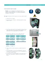
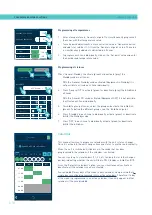
Pneumatic connection
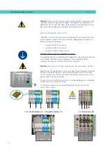
Before connecting the pneumatic power to the vacuum feeder, make sure
the pressure regulator on the system and the main air supply is completely
closed.
Connect the vacuum feeder through a flexible tube with outside diameter of 10
mm to the general air supply (6 bar max.) (1). The unit has a quick coupling for
this connection.
The air outlet grid (2) is connected by a flexible hose outside diameter 10 mm
to the Y quick connector (3) located in the area of the suction adhesive.
To be sure about the connection of the tubes in the inlet and the outlet, the
valve is marked with the numbers 1 and 2 respectively. See the pictures.
Once connected, open the air supply verify that you have maximum 6 bar
pressure. Pressures higher than that causes an unnecessary expense and
the possibility to produce turbulences in the hot melt tank with consequent
malfunction of the unit.
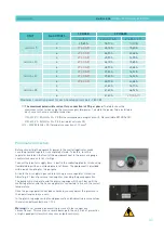
Suction tube connection
The suction tube should be connected to the swievel elbow of the vacuum
feeder, inserting it into the inside of the metallic mouth down to its bottom.
Place the swievel elbow to the most convenient position for installation,
depending on the location of the hot melt container.
Therefore:
• Loose slightly the three fixing screws for the lid of the filter and set
the swievel elbow.
• Place the swievel elbow to the desired position, twisting it in the
required sense.
• Tight the three fixing screws to the position of the elbow and prevent
their movement.
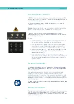
Placing the suction tube
To transfer the adhesive from the adhesive container to the hot melt
equipment, the suction tube should be inserted to the bottom of the container.
The four flaps that protects the entrance of the suction tube are designed to
keep the suction mouth open and without obstructions. It maintains a free
way for the suctioned adhesive.
3
1
2
Summary of Contents for Micron + 10
Page 10: ...FOCKE MELER GLUING SOLUTIONS TABLE OF CONTENTS This page is intentionally left blank ...
Page 38: ...FOCKE MELER GLUING SOLUTIONS INSTALLATION 3 16 This page is intentionally left blank ...
Page 74: ...FOCKE MELER GLUING SOLUTIONS 4 36 MELTER OPERATION This page is intentionally left blank ...
Page 84: ...FOCKE MELER GLUING SOLUTIONS 5 10 MAINTENANCE This page is intentionally left blank ...
Page 91: ...MA 5162 ENG MICRON PISTON ADHESIVE MELTER ELECTRICAL DRAWINGS 7 1 7 ELECTRICAL DRAWINGS ...
Page 92: ...FOCKE MELER GLUING SOLUTIONS 7 2 ELECTRICAL DRAWINGS This page is intentionally left blank ...
Page 102: ...FOCKE MELER GLUING SOLUTIONS 8 10 PNEUMATIC DIAGRAM This page is intentionally left blank ...
Page 104: ...FOCKE MELER GLUING SOLUTIONS 9 2 SPARE PARTS LIST This page is intentionally left blank ...