


FOCKE MELER GLUING SOLUTIONS
INSTALLATION
3-12
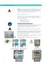
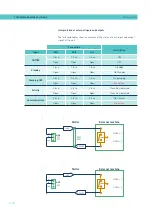
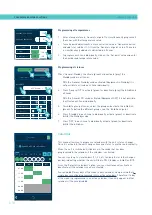
Connecting zone inhibition
Attention:
it is necessary that all inhibition imput cables are shielded.
In the melting equipment, the shield must be connected outside, in the
equipment chassis or in the connector prepared for this purpose in
some models.
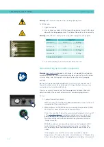
Warning:
Risk of electric shock. Carelessness may cause injury or death.
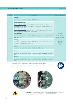
1. Disconnect the unit’s power.
2. Open the front door of the electric cabinet by giving the fastening screw
a 1/4 turn.
3. Run the signal cable (max. Ø14mm) through the bushing at the rear of
the unit and attach it to the interior fitting, taking care to ensure that
the cable reaches the connectors (X21 / X9) in the temperature control
board.
4. Remove the connectors from the board and connect the cable wires to
their corresponding terminals. To activate it, all disabling signals must
be switched with the GND pin.
5. Reconnect the connectors to the board.
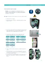
6. Check that the cable is correctly connected and that its passage
through the electric cabinet presents no risk of jamming, being cut or
any other accidental damage.
7. To configure the various inhibition groups and assign them the
corresponding signal, see point ‘4 Use / Heating Menu / Inhibitions’’.
X9
X21
+24
8
7
6
5
GND
+24
4
3
2
1
GND
X
é é é é é
X
é é é é é
X21
X9
P
Summary of Contents for Micron + 10
Page 10: ...FOCKE MELER GLUING SOLUTIONS TABLE OF CONTENTS This page is intentionally left blank ...
Page 38: ...FOCKE MELER GLUING SOLUTIONS INSTALLATION 3 16 This page is intentionally left blank ...
Page 74: ...FOCKE MELER GLUING SOLUTIONS 4 36 MELTER OPERATION This page is intentionally left blank ...
Page 84: ...FOCKE MELER GLUING SOLUTIONS 5 10 MAINTENANCE This page is intentionally left blank ...
Page 91: ...MA 5162 ENG MICRON PISTON ADHESIVE MELTER ELECTRICAL DRAWINGS 7 1 7 ELECTRICAL DRAWINGS ...
Page 92: ...FOCKE MELER GLUING SOLUTIONS 7 2 ELECTRICAL DRAWINGS This page is intentionally left blank ...
Page 102: ...FOCKE MELER GLUING SOLUTIONS 8 10 PNEUMATIC DIAGRAM This page is intentionally left blank ...
Page 104: ...FOCKE MELER GLUING SOLUTIONS 9 2 SPARE PARTS LIST This page is intentionally left blank ...