


MA-5162-ENG
PISTON ADHESIVE MELTER
INSTALLATION
3-7
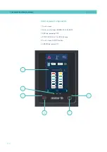
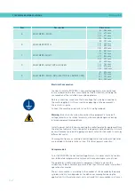
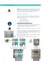
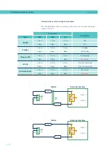
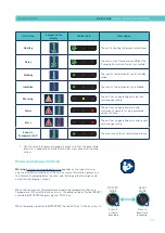
The signals that can be used to communicate with the main machine are as
follows:
Type
(1)
Description
Terminal/Connector
Input
External ON/OFF
A closed contact switches the unit on; an open contact turns it off.
Terminal
XDI1.1 / XDI1.2
XDI2.1 / XDI2.2
------
Connector on
HMI card
(5)
DI3
Standby ON/OFF
A closed contact activates the ‘Standby’ function; an open contact deactivates it
and the unit returns to the status indicated by the unit’s other signals.
Pumping external OFF
A closed contact activates pumping (if the required conditions are met); an open
contact deactivates it.
Activity (Auto Standby - OFF)
Contact for the activity control signal, to switch the unit to Standby and off
mode
(2)
.
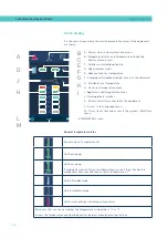
ON/OFF communications
A closed contact activates the communications (Modbus/Profibus); an open
contact deactivates them. Signals must be enabled in the unit
(3)
.
Inhibition of zones
Zone inhibition control inputs. The unit has 8 contacts to inhibit 8 groups of
programmable zones
(4)
. When the contact is closed, the respective group is
inhibited (off); when the contact is open, the inhibition of that group is disabled
(activated).
Temperature Control
Board
X21 (Signals 1 to 4)
X9 (Signals 5 to 8)
Product passage signal (Flowmeter)
Digital input to connect a photocell or product passage signal when the unit has
the flow control installed
(6)
.
Terminal
(5)
X
(1) See point ‘4 Use / Settings Menu / Configuration of input and output signals’.
Some inputs will not be shown on the menu, depending on which options are installed in the unit.
(2) See point ‘4 Use / Heating Menu / Auto Standby - OFF’.
(3) See point ‘4 Use / Settings Menu / Additional Settings’.
(4) See point ‘4 Use / Heating Menu / Inhibitions’
(5) Connectors available according to options installed on the equipment.
(6) See point ‘4 Use / Flowmeter’
X9
X21
DI3
X
Summary of Contents for Micron + 10
Page 10: ...FOCKE MELER GLUING SOLUTIONS TABLE OF CONTENTS This page is intentionally left blank ...
Page 38: ...FOCKE MELER GLUING SOLUTIONS INSTALLATION 3 16 This page is intentionally left blank ...
Page 74: ...FOCKE MELER GLUING SOLUTIONS 4 36 MELTER OPERATION This page is intentionally left blank ...
Page 84: ...FOCKE MELER GLUING SOLUTIONS 5 10 MAINTENANCE This page is intentionally left blank ...
Page 91: ...MA 5162 ENG MICRON PISTON ADHESIVE MELTER ELECTRICAL DRAWINGS 7 1 7 ELECTRICAL DRAWINGS ...
Page 92: ...FOCKE MELER GLUING SOLUTIONS 7 2 ELECTRICAL DRAWINGS This page is intentionally left blank ...
Page 102: ...FOCKE MELER GLUING SOLUTIONS 8 10 PNEUMATIC DIAGRAM This page is intentionally left blank ...
Page 104: ...FOCKE MELER GLUING SOLUTIONS 9 2 SPARE PARTS LIST This page is intentionally left blank ...