


FOCKE MELER GLUING SOLUTIONS
4-6
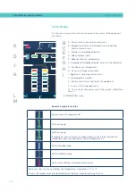
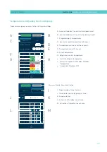
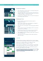
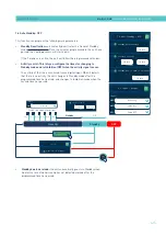
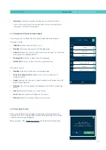
MELTER OPERATION
A - Alarms status and alarms menu access.
B - Temperature status and Temperature and Heating
Shortcut menu access.
C - Calendar activated/deactivated.
D - Adhesive level status.
E - Adhesive tank real temperature.
F - Pumping activated/deactivated. Access to the flowmeter.
G - Distributor real temperature.
H - Hoses real temperature zones.
I - Applicators real temperature zones.
J - Hose/applicator symbol.
K - Pattern controller connected to the equipment.
L - Access to the Language menu
M - The system’s time and access to the system’s Date/Time
menu.
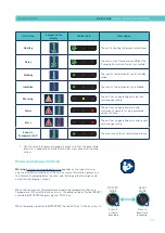
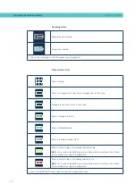
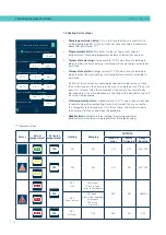
General temperature status
to MAIN MENU screen
Active zones in Temperature OK.
Unit heating up.
08:31
Unit heating up.
‘Pumping Permission Delay’ countdown timer, once all the active heated
components have reached their set point temperature ± 3°.
Unit in Standby mode.
Unit in Inhibition mode.
Unit in overheating or low temperature alarm.
Moreover, this icon shows whether the temperature is indicated in °C or °F.
Access the Temperature and Heating Shortcut displays menu by pressing the icon
.
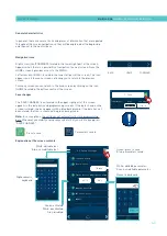
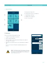
PISTÓN
HMI
: S02001101 v1.1.2
TC
: S02200100 v1.0.84
IO FM : XXXXXXXXX vx.x.x
154
154
A
15:35
°C
08:31
185
170
1
154
154
2
100
100
3
---
---
4
5
42
42
6
B
A
B
D
J
H
C
L
E
G
I
K
F
M
Home display
It is the main screen where the most representative values of the equipment
are shown.
Summary of Contents for Micron + 10
Page 10: ...FOCKE MELER GLUING SOLUTIONS TABLE OF CONTENTS This page is intentionally left blank ...
Page 38: ...FOCKE MELER GLUING SOLUTIONS INSTALLATION 3 16 This page is intentionally left blank ...
Page 74: ...FOCKE MELER GLUING SOLUTIONS 4 36 MELTER OPERATION This page is intentionally left blank ...
Page 84: ...FOCKE MELER GLUING SOLUTIONS 5 10 MAINTENANCE This page is intentionally left blank ...
Page 91: ...MA 5162 ENG MICRON PISTON ADHESIVE MELTER ELECTRICAL DRAWINGS 7 1 7 ELECTRICAL DRAWINGS ...
Page 92: ...FOCKE MELER GLUING SOLUTIONS 7 2 ELECTRICAL DRAWINGS This page is intentionally left blank ...
Page 102: ...FOCKE MELER GLUING SOLUTIONS 8 10 PNEUMATIC DIAGRAM This page is intentionally left blank ...
Page 104: ...FOCKE MELER GLUING SOLUTIONS 9 2 SPARE PARTS LIST This page is intentionally left blank ...