M2D-Laser-Scanner with Ethernet-Interface
Manual
HB-M2D-Ethernet-E
Page 26 of 39
www.MElsensor.com
E
E
x
x
a
a
m
m
p
p
l
l
e
e
c
c
o
o
d
d
e
e
f
f
o
o
r
r
S
S
o
o
f
f
t
t
w
w
a
a
r
r
e
e
e
e
n
n
g
g
i
i
n
n
e
e
e
e
r
r
s
s
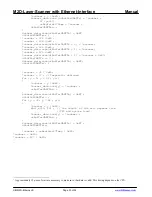
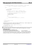
Our software-engineers use Delphi and C++ (Visual Studio). Example code may be released in C++, Ruby or
Delphi. We will not be able to supply code in VB or other dialects.
Disclaimer:
MEL does not make warranty for correct function and completeness of the example code nor does
MEL assume that code fragments are bug free. The use of the example code is at customers risk and with the
sole responsibility of the customer’s software engineers. MEL can not take any responsibility, that the code
provided is free from third party rights, pending software patents or bug free.
D
D
a
a
t
t
a
a
f
f
o
o
r
r
m
m
a
a
t
t
f
f
o
o
r
r
r
r
e
e
g
g
i
i
s
s
t
t
e
e
r
r
a
a
d
d
d
d
r
r
e
e
s
s
s
s
e
e
s
s
a
a
n
n
d
d
c
c
o
o
m
m
m
m
a
a
n
n
d
d
s
s
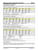
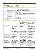
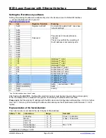
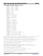
MSB (Bit 7) is used as a differentiator between register addresses and command or data:
MSB (Bit 7) = “0” for all register addresses
MSB (Bit 7) = “1” for all commands and data
To change a value, transmit first the register number and then the new value. The register number remains set,
until a new register number or a value is sent. It is not possible to read the registers. Dual registers: the value is
active only when the high byte has been transferred.
Bit
order
register
data
register
data
Lo-Byte
Lo-Byte
Hi-byte
Hi-byte
76543210 76543210
76543210 76543210
0xxxxxxx
1xxxxxxx
0xxxxxxx 1xxxxxxx
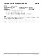
Software Examples
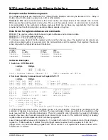
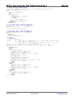
1. Switch on / Off FPGA-LED
Lo-Byte Hi-Byte
0x0B
0x80 // LED on
0x0B
0x81 // LED off
0x0B = register address (decimal 11)
0x80 = command: set LED on
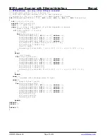
2. Set Laser intensity in manual mode: set register 0x15 = 1
Lo-Byte Hi-Byte
0x00 0xff 0x01 0x87 0x3FF
//
laser
off
0x00 0x80 0x01 0x80 0x000
//
Laser
full
power
0x00 0x8F 0x01 0x84 0x0x20F
// Laser 527 decimal; range = 0…1022; 1023 = 0ff
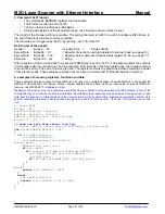
masking is done a prevention method:
Byte
0:
0x00
register
address
Byte 1:
(0x20F & 0x7F) | 0x80
data of Lo-Byte
Byte
2:
0x01
register
address
Byte 3:
(0x20F>>7)& 0x7F | 0x80
data Hi-Byte
Used logic function terms
>>7 = shift right by 7 bit
&
= binary (bit by bit) AND
|
= binary (bit by bit) OR
0x7F = mask
The mask is used to prevent false readings
Lo and Hi-Byte can be sent either in separate chunks or in one “telegram”. There will be no difference for the
controller. A telegram may make up to 4 Byte. The received register values are written to the registers as they
were received from the incoming data stream. There is no specific order of sending the register information,
except a few ones, which provide a specific mode like set trigger mode on. The method of “writing” or “reading”
register address and data applies to all of the following registers.
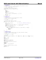
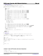
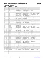
Laser Video gain default value is 950 (register 6 + 7), register 0x15 set to 0 (= automatic control). Note: changing
register 6 + 7 affects visibility of profiles. Using the trigger feature requires to set the register 0x14 Bit 3 to “1”
(trigger mode = on), before accessing register 0x1D. Do not use Bit 0 .. 2 of register 0x14, these are reserved for
hardware Rev.1 features.


