M2D-Laser-Scanner with Ethernet-Interface
Manual
HB-M2D-Ethernet-E
Page 4 of 39
www.MElsensor.com
S
S
y
y
s
s
t
t
e
e
m
m
d
d
e
e
s
s
c
c
r
r
i
i
p
p
t
t
i
i
o
o
n
n
The M2D
-LAN
-Laser-Scanners come with an electronic box in the size of 102 x 70 x 28 mm. A standard RJ-45-
Ethernet connector is in the cover of the electronic system box. On the D-Sub-25-pin connector at the side, the
Ethernet-signals are also available. When the Ethernet is connected to the D-Sub connector, the cover may be
sealed optional, providing immunity against water and dust.
S
S
c
c
a
a
n
n
n
n
e
e
r
r
H
H
e
e
a
a
d
d
,
,
E
E
l
l
e
e
c
c
t
t
r
r
o
o
n
n
i
i
c
c
-
-
S
S
y
y
s
s
t
t
e
e
m
m
a
a
n
n
d
d
c
c
o
o
n
n
t
t
r
r
o
o
l
l
s
s
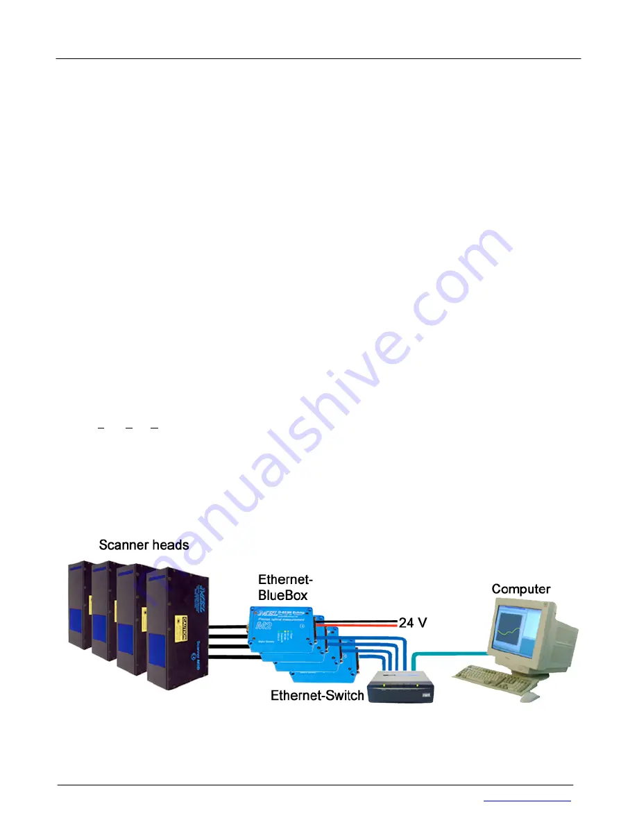
The Scanner head is equipped with a CCD-Camera, a Line Laser projector and a electronic system for the
detection of the profile from the camera video signals. The Scanner head is connected to the Blue-Box with a 9-
pin Sub-D-connector. The camera in the scanner head is controlled through the Blue-Box. There are no Dip-
Switches for adjustment of shutter time, video gain and laser intensity. All adjustments are done in the
configuration software and permanently stored in a electrically erasable EPROM.
For software engineers, writing their own applications, MEL deploys examples with source-code in C++. For
documentation of hardware registers, scanner implementation and data format see Data format and interface
description.
S
S
o
o
f
f
t
t
w
w
a
a
r
r
e
e
C
C
o
o
n
n
t
t
r
r
o
o
l
l
l
l
e
e
d
d
P
P
a
a
r
r
a
a
m
m
e
e
t
t
e
e
r
r
s
s
TCP/IP:
address; subnet mask; TCP-ports
Operation controls:
shutter control
Laser “intensity” control; Video gain control
Operation modes:
continuous - single shot; ext. trigger – free run
Synchronized – non-synchronized mode , Trigger with hardware / software
C
C
o
o
n
n
n
n
e
e
c
c
t
t
i
i
n
n
g
g
t
t
h
h
e
e
E
E
t
t
h
h
e
e
r
r
n
n
e
e
t
t
-
-
S
S
c
c
a
a
n
n
n
n
e
e
r
r
When connecting the M2D
-LAN
-Scanner to a your LAN* use a 1:1 wired cable to the Ethernet-Switch, when
connecting directly to the Ethernet network card in the PC, use a cross-wired Ethernet cable, also known as
crossover-cable (X-over). Do not connect Ethernet card and Scanner with a 1:1-wired Ethernet cable!
* LAN = Local Area Network
U
U
s
s
i
i
n
n
g
g
s
s
t
t
a
a
n
n
d
d
a
a
r
r
d
d
E
E
t
t
h
h
e
e
r
r
n
n
e
e
t
t
h
h
a
a
r
r
d
d
w
w
a
a
r
r
e
e
When testing transmission of the TCP data from the scanner, with standard hardware from the shelf no problems
have been found so far concerning Ethernet Switches and CAT-5e cables. Testing included sending the profiles
over the company network and wireless LAN (802.3g).
We do not recommend the use of „Hubs“: Hubs connect the ports in parallel, this may cause hangs on data
transmission or loss of information.
When “a bunch of scanners” were controlled by a PC, the PC and the graphic card must have good performance
in order to capture and process and display all scanners data fast enough. We recommend to check the image
numbers transmitted with every scan profile. See data format description Register Sync+Status Byte 11, page ….
for details.


