M2D-Laser-Scanner with Ethernet-Interface
Manual
HB-M2D-Ethernet-E
Page 6 of 39
www.MElsensor.com
E
E
t
t
h
h
e
e
r
r
n
n
e
e
t
t
c
c
o
o
n
n
n
n
e
e
c
c
t
t
o
o
r
r
s
s
R
R
J
J
-
-
4
4
5
5
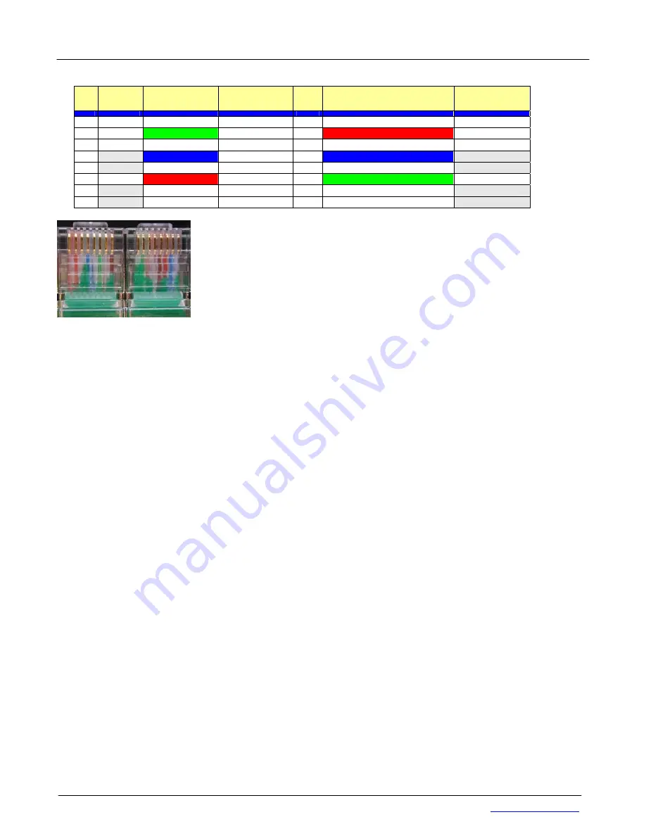
Pin Signal connector A connector B
“normal”
Pin Connector B
“crossed”
Signal
1 TX
+
Green +White
Green +White
1
Red + White
Rx +
2 Tx
-
Green
Green 2
Rot
Rx -
3 Rx
+
Red + White
Red + White
3
Green +White
Tx +
4 nc -
Blue
Blue 4
Blue
nc -
5 nc +
Blue + White
Blue + White
5
Blue + White
nc +
6 Rx
-
Red
Red 6
Green
Tx -
7 nc +
Brown+ White
Brown+ White
7
Brown+ White
nc +
8 nc -
Brown
Brown 8
Brown
nc -
picture left: crosslink cable
direct connection from PC network card to scanner electronic box requires a
crosslink network cable. The position of the red and blue wires in the connectors
shows, that this cable is a crossed Ethernet cable, known as crosslink. When you
use a Ethernet switch, 1:1 patch cables should be used instead.
M
M
u
u
l
l
t
t
i
i
-
-
S
S
c
c
a
a
n
n
n
n
e
e
r
r
A
A
r
r
r
r
a
a
y
y
s
s
Setting up a multi-scanner array will not require specific “programming”. Configuration can be copied from one
Scanner to the next, yet the TCP/IP addresses of each scanner must then be set to
different
IP-address value.
(see pages …).
Theoretically it is possible to connect more than 30 Scanners in one 100 Mbit Ethernet network
segment, providing no more than 50% load of the 100 Mbit network. Using 10 Mbit network equipment is not
recommended. Image data transmission and network performance
Standard Ethernet network switches, network cards and PC have no problems with M2D-Ethernet-Scanners.
When connecting multiple scanners to one PC, the PC must have enough performance to receive, process and
display the Scan profile information retrieved from the scanners. The performance of CPU and graphic card could
cause “dropped frames”. Use the image count number, delivered with the scan profile data (see data format
description, table 5 on page 12, status register Byte 11 ( 0 … 254) to detect lost profiles!
H
H
o
o
w
w
m
m
a
a
n
n
y
y
s
s
c
c
a
a
n
n
n
n
e
e
r
r
s
s
c
c
o
o
u
u
l
l
d
d
b
b
e
e
i
i
n
n
t
t
e
e
g
g
r
r
a
a
t
t
e
e
d
d
i
i
n
n
o
o
n
n
e
e
n
n
e
e
t
t
w
w
o
o
r
r
k
k
s
s
e
e
g
g
m
m
e
e
n
n
t
t
?
?
The Scanner sends out 100 scan profiles per second with the following data:
o
TCP-IP header
o
M2DF-L-header, Scan profile data, reserved Bytes
o
Additional information as encoder data, fill Bytes, FiFO-fill level data
o
CRC error check data
Each scan profile with above data is packed into a 2048 Byte block = 100 x 2.048 kBytes / s = 204,8 kBytes /s
The 100 Mbit network = 12.500 kBytes / s could transport 12.500 / 226 = 61.03 Scanners. For real-time
applications, Administrators avoid network load above 50%. Therefore the recommendation = max. number of
scanners = 30.
C
C
o
o
n
n
t
t
r
r
o
o
l
l
C
C
o
o
m
m
m
m
a
a
n
n
d
d
s
s
With the exception of “Laser-ON”, there is no other command to be sent for activation of the scanner. When the
Laser is on, the scanner sends profile data as a “continuous stream”.
It is highly recommended, to send a first “FIFO reset” command, before measurements were made in regular
intervals. The command “FiFO-reset” destroys the first image (at least partially). Therefore ignore the first image
after “FiFO-reset” and wait for the second one. The command FiFO-reset makes sense, when no data has been
acquired for a long time, and the scanner has been waiting for new data. When data is read continuously, the
command FiFO-reset is not useful.
Commands for set up of trigger mode and sync mode are given in the data format description, page 14 and 19.


