M2D-Laser-Scanner with Ethernet-Interface
Manual
HB-M2D-Ethernet-E
Page 27 of 39
www.MElsensor.com
3.
Command: 0x21 (dump)
o
The complete 64 EEPROM registers are transmitted
o
The Protocol version is set to 0x10h
o
The Sync raster is written as 8-Null Bytes
o
Starting with Byte 64 of the Scan-Data range, the Firmware-Version number is sent.
The length of the Firmware-String is variable. The ending character is 0x00h. In each block data is 2048 Bytes. In
the end of the block, old data could be contained.
The transmission is triggered by the PC by sending „0x21“ from the PC.
Data format of the packet:
Header =
Bytes 0 ... 65
including Sync =
8 Bytes 0x00h
Eprom Data
Bytes 66 ... 97
= Register of electronic unit (data related to scanner head, see page 14)
Eprom Data
Bytes 98 ... 129
= Register Eprom data (user data at status register 32..63, see page 17)
Firmware
Bytes 130 ...xxx
= String
After reception of the command 0x21h a packet of 2048 Bytes is sent to the PC. The packet contains the contents
of all registers who can be read out, but no scan data. From Byte 64 of the Scan-data range, the firmware version
is sent out as string. The end of the string is 0x00. The register contents are determined when switching on power
of the electronic box. These values are stored until next reset (command 0x1F= Reset Ethernet) in memory.
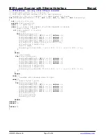
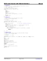
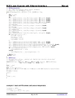
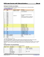
4. examples of accessing registers, functions and data
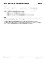
These examples have been taken from the M2Dmini.c. For use as a complete package, download M2Dmini.c and header file
M2Dmini.h from the MEL FTP-Server. Please consider updates and bug fixes, when you have earlier versions of M2Dmini.
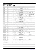
[version = as of 2006-08-10]
Headlines in blue!
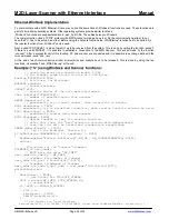
Disclaimer: the given source code examples were taken from a collection of modules used with ISA hardware. Some of the
commands may not work with the Ethernet hardware. Nevertheless these examples may show basic techniques how to read
data from the scanner. In future releases of the documentation will be bundled into a separate documentation and be more
specific considering this aspect. Source codes were given on a basis of “test and verify – then use it for free and on your own
risk”.
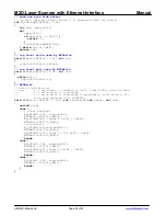
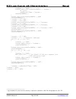
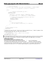
// Linux RTAI
#ifdef __RT__
#define inp(port) inb(port)
#define inpw(port) inw(port)
#define outp(adr,val) outb(val,adr)
#endif /* __RT__*/
// read one byte from sensor (one try)
// return 0xFF if sensor busy of FiFO empty (nothing read)
int ByteFromM2FF(M2Dinfo *inf)
{
if(inf->m2FirstByte){
inf->m2FirstByte=0;
inf->m2Word=inpw(inf->ioPort);
#ifdef debug
M2Dwait(inf, wait_cnt);
if(inf->bbf){
if(!(remove_ffff && inf->m2Word==0xFFFF)){
inf->bbf[inf->bbf_pos]=inf->m2Word;
inf->+;
if(inf->bbf_pos==BBF_ANZ) inf->bbf_pos=0;
}
}
#endif
return inf->m2Word & 0xFF;
}
else{
inf->m2FirstByte=1;
return (inf->m2Word >> 8) & 0xFF;
}
}


