background image

Q-Sense Technical Reference Manual 


Proprietary 

72 of 188 


Increase Rate 
(°C/sec) 

Defines the temperature rate of increase per second, from the 
destination temperature down to the baseline. 
Type an acceptable value:  . 0.1- 2°C/sec for Q-sense thermode. 

Decrease Rate 
(°C/sec) 

Defines the temperature rate of decrease per second, from the 
baseline until a response is recognized. 
Type an acceptable value:  .. 0.1-1°C/Sec for Q-sense thermode  

Number of stimuli 

The number of required subject responses until test 
termination. 

Standard Events 

Enables the system to alert you when stimulation procedure 
arrives at specific standard events.  


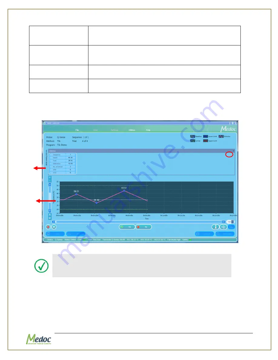
The following screen shows a sequence consisting of TSL Method Test: 


Figure 37: A TSL Method Test  


Test statistics are hidden by default. 

The bottom of the screen displays the total records (sequences) in 
the current program. 


To view the statistics details, place the cursor at the bottom end of the statistics tab and drag 
it down. 

Click the Tack icon at the upper right of the screen to lock or unlock the statistics display 
(indicated by the circle in 

Figure 37

). 

Statistics tab 

Baseline 
Temperatur

Summary of Contents for TSA 2001

Page 1: ...Proprietary 1 of 188 Small Fiber Test Technical Reference Manual ...

Page 2: ...Yishai 3004627 ISRAEL Tel 972 4 9038800 Fax 972 4 9038808 E Mail medoc medoc web com www medoc web com Medoc U S A Compass Medical Technologies Inc 1502 West Highway 54 Suite 404 Durham North Carolina 27707 U S A Tel 1 919 402 9600 Fax 1 919 402 9607 E Mail medoc mindspring com European Authorized Representative CEpartner4U BV Esdoornlaan 13 3951 DB Maarn The Netherlands Phone 31 343 442 524 Fax 3...

Page 3: ...Labels Symbols Warning Statements and Abbreviations 19 1 8 Electromagnetic immunity 20 1 9 Recommended Separation Distance between Portable and Mobile RF Communications Equipment and Q Sense 24 1 10 Technical Data 25 2 Overview 27 2 1 Training 27 2 2 System Description 27 2 3 Q SENSE Thermode 27 2 4 Terminology 27 2 5 System Status 28 2 6 System States 28 2 7 Application Methods 29 2 7 1 Limits Me...

Page 4: ...5 4 4 Current Selection Information 48 5 4 5 Data Display Area 48 5 4 6 Q Sense Status Line 48 6 Test Procedure and Management 49 6 1 Selecting a Patient 49 6 2 Selecting a Program 50 6 3 Selecting a Body Site 52 6 4 Running the Test 53 6 4 1 Test and Post Test Options 55 6 4 2 Temperature Graph Display 56 6 4 3 Test Run Keyboard Shortcuts Hot Keys 56 7 Program Management 58 7 1 Program List 58 7 ...

Page 5: ...nt 88 8 7 Import Export Patient Lists 88 9 Results Management 90 9 1 Results List 90 9 2 Import Export Results 92 9 3 Print Results and Reports 95 9 3 1 Analysis Report Dialog 95 10 System Configuration 105 10 1 Software Settings 105 10 1 1 Communication 106 10 1 2 Patient Fields 106 10 1 3 Results Fields 110 10 1 4 Report Options 110 10 1 5 User Management 116 10 2 Hardware Settings 123 10 2 1 Ge...

Page 6: ...0 17 3 Periodical Thermode Maintenance 150 18 Appendix F Cleaning and Disinfecting 151 19 Appendix G Thermode straps assembly instructions 152 20 Appendix H List of Accompanying Documents 153 21 Appendix I Transportation and Storage conditions 154 22 Appendix J Environmental Conditions 155 23 Appendix K Upgrading procedure 156 24 Appendix L Troubleshooting Operator Level 158 24 1 Numbered Software...

Page 7: ...182 26 1 fMRI Thermode 182 26 1 1 Q sense system configuration in fMRI mode 182 26 1 2 Installation MR Filter 183 26 2 TTL functionality 186 26 2 1 Q sense fMRI side panel 186 26 2 2 TTL set up 186 26 2 3 Standard Event Configuration 187 26 2 4 TTL specifications 187 26 3 Blower control 188 ...

Page 8: ...h Screen 43 Figure 16 Self Test Prompt 44 Figure 17 Q Sense in Rest Mode 45 Figure 18 Test Navigator Main Menu 45 Figure 19 Test Management Main Screen 49 Figure 20 Patient Selection Menu 50 Figure 21 Program Selection Menu 51 Figure 22 Select Body Site screen 52 Figure 23 Select Body Site Specific site selection 53 Figure 24 Pre Test Screen 54 Figure 25 Real Time Test 56 Figure 26 Program Managem...

Page 9: ...port Result File Opened In Excel Data Tab Sample 93 Figure 55 Analysis Reports Dialog 95 Figure 56 Analysis Report 96 Figure 57 Single Results Report 98 Figure 58 Multiple Results Report 98 Figure 59 Site to Site Results Report 100 Figure 60 Pre Post Results Report 100 Figure 61 Trend Results Report 100 Figure 62 Custom Report Results 100 Figure 63 Bilateral Results Report 101 Figure 64 Custom Rep...

Page 10: ...Normative Data 137 Figure 94 Normative Data License Agreement 138 Figure 95 Normative Data Editor Learn More 139 Figure 96 Normative Data screen select source 140 Figure 97 Normative Data Editor 141 Figure 98 Database Utility Backup Restore Menu 144 Figure 99 System Diagram 148 Figure 100 Previous version message 156 Figure 101 Removing previos version screen 156 Figure 102 Data Backup Path 156 Fi...

Page 11: ...fMRI Thermode Control Room part WA 00281 184 Figure 117 Q sense fMRI Thermode Shielded room part AS 00412 185 Figure 118 Q sense fMRI side panel 186 Figure 119 HW settings for Q sense fMRI 186 Figure 120 Standard Events in Program Editor 187 Figure 121 Standard Event Editor 187 ...

Page 12: ...4 Table 18 Program Parameters 75 Table 19 Chain sub program parameters 77 Table 20 Program Details 77 Table 21 Program Table 78 Table 22 List of standard events according to program type 80 Table 23 Report Analysis Configuration 96 Table 24 Report Analysis Configuration 101 Table 25 Software Settings General 106 Table 26 Patient s Field 110 Table 27 Report Options 111 Table 28 Report Options 113 T...

Page 13: ...l Proprietary 13 of 188 Table 39 Accessories 145 Table 40 Q sense Accompanying Documents 153 Table 41 Warnings 158 Table 42 Errors 162 Table 43 Faulty System Responses 171 Table 44 Regular Characters 177 Table 45 Special Characters 177 ...

Page 14: ...nd fully understood paying particular attention to all 1 Warnings 2 Cautions 3 Notes 4 Important Notices 5 User Notices 1 1 User Manual Icons The following icons are used throughout the user manual Disclaimer Medoc assumes no liability for use of this document if any unauthorized changes to the content or format have been made Every care has been taken to ensure the accuracy of the information in ...

Page 15: ...suffering from wide range of neuropathic CNS and pain conditions Minimum age reported in the literature is 6 The only known contraindication is related to the skin on which the thermode is applied it must be used in contact with intact skin only The thermode also intended to be applied on the skin only not on the eyes and the mouth 1 4 Safety and Regulatory Summary Read and follow all WARNINGS CAU...

Page 16: ...ot supplied by Medoc Medoc s power supply Cat DT 00017 Do not use any electrode paste gel or other materials on the contact point between the Thermode plate and the skin of the tested subject To reduce the risk of injury place the Thermode on the subject only before starting the test and while the test screen is visible After the test is complete remove the Thermode from the subject s skin while t...

Page 17: ...t is used in a residential environment for which CISPR 11 class B is normally required this equipment might not offer adequate protection to radio frequency communication services The user might need to take mitigation measures such as relocating or re orienting the equipment 1 5 2 Cautions Proper use of this device depends on careful reading of all instructions and labels Turn OFF system power be...

Page 18: ... to protect the tested subject and the unit Software protection mechanisms include Temperature upper and lower limits In normal operation Thermode temperature will always be within these limits Time duration limits Thermode temperature is limited in duration If the Thermode temperature maintains a specific temperature or above for a longer period of time then specified for that temperature the sys...

Page 19: ...pment Labels Equipment Label Description Power switch ON OFF COM Communications connector Date of Manufacture YYYY MM Manufacturer Degree of protection against electric shock Applied Part Type BF Warning Connect the power cord to the power outlet according to the local electrical standards Refer to Manual Disposal according to electronic scrap ordinance I O ...

Page 20: ...50 60 Hz Power frequency magnetic fields should be at levels characteristic of a typical location in a typical commercial or hospital environment Electrical fast transient burst IEC 61000 4 4 2 kV for power supply lines 2 kV for power supply lines Mains power quality should be that of a typical commercial or hospital environment Surge IEC 61000 4 5 1 kV line s and neutral 1 kV line s and neutral M...

Page 21: ...Q Sense Technical Reference Manual Proprietary 21 of 188 95 dip in UT for 5s 95 dip in UT for 5s NOTE UT is the a c mains voltage prior to application of the test level ...

Page 22: ...equipment should be used no closer to any part of the Q sense including cables than the recommended separation distance calculated from the equation applicable to the frequency of the transmitter Recommended separation distance where P is the maximum output power rating of the transmitter in watts W according to the transmitter manufacturer and d is the recommended separation distance in metres m ...

Page 23: ...r relocating the Q Sense Over the frequency range 150 kHz to 80 MHz field strengths should be less than 3 V m Declaration electromagnetic emissions Emissions test Compliance Electromagnetic environment guidance RF emissions CISPR 11 Group1 Class A The Q sense uses RF energy only for its internal function Therefore its RF emissions are very low and are not likely to cause any interference in nearby...

Page 24: ...eparation distance according to frequency of transmitter m 150 kHz to 80 MHz outside ISM bands 150 kHz to 80 MHz in ISM bands 80 MHz to 800 MHz 800 MHz to 2 5 GHz 0 01 0 12 0 2 0 4 1 0 1 0 37 0 64 1 3 2 6 1 1 17 2 4 8 10 3 7 6 4 13 26 100 11 7 20 40 80 For transmitters rated at a maximum output power not listed above the recommended separation distance d in metres m can be estimated using the equa...

Page 25: ...ntervals Short pause between patients may be required Minimum Inter Stimuli Interval ISI 2 sec Maximum Consecutive Stimuli 10 Baseline Thermode Temperature Range 28 40 C Programmable Parameters Method Adaptation Temperature Heating Rate Cooling Rate Number of Stimuli ISI Sound Option Randomize Option Communication with PC USB Communication with Printer Via PC Standards IEC 60601 1 IEC 60601 1 2 Ap...

Page 26: ...hnical Reference Manual Proprietary 26 of 188 Parameter Specification Screen Resolution 1366X768 and higher Patient Response Unit 2 buttons Yes No Response Unit Product life time 10 years Thermode life time 1 year ...

Page 27: ...nent of the system which delivers the actual stimulus The main components of the Q Sense Thermode include Active Thermal Element The active Thermal element is a Thermoelectric Cooler TEC a peltier element which generates a temperature gradient according to the direction and amplitude of power electrical current it is given Temperature Sensors Thermistors The Thermistors are resistors which change ...

Page 28: ...is no access to the Q SENSE hardware settings The Simulator is useful for demonstration training and for protocol design without executing actual thermal stimulation It is recommended to turn off the Q SENSE system while working in Simulator mode 2 6 System States System State is the active state in which the system is currently operating System states refer to the online status only The Q SENSE a...

Page 29: ...ceives a predefined sensation he she manually stops the stimulus The Limits method is the most widely used method for threshold determination because it requires the shortest test procedure of all methods and it can measure not only pain thresholds but also non painful thermal thresholds For detailed information refer to section 7 6 1 page 62 2 7 2 Levels Method In the Levels method stimuli are in...

Page 30: ... Sequence Onset to Onset Time Trial 1 Trial 2 End to Onset Time Sequence 1 Start Test End Test Figure 2 Ramp Hold Sequence Return to Baseline Each sequence consists of a number of similar trials one trial is also allowed 1 The start point of each trial is called onset The temperature at this point the onset point is the Baseline Temperature defined for this sequence 2 From this point the temperatu...

Page 31: ...te the perceived magnitude of pain The intensity of the next stimulus is set according to the response increases if the reported pain rating is lower than the desired decreases if the reported pain rating is higher than the desired The step size by which the intensity of the next stimulus is changed can be predetermined during program creation or set by the operator during the test The VAS Search ...

Page 32: ...e are predetermined during program creation and the temperature of each trial is defined according to these parameters and the subject reported pain rating increases by the step size value if the reported pain rating is lower than the target and decreases by the step size value if the reported pain rating is higher than the target See section 7 6 5 page 75 for full description of program details a...

Page 33: ...h 1 Q sense Thermode Main receptacle Blue power connector Green Sensor connector 2 Response Unit receptacle Use for recording patient response during test Table 5 Connectors to power side panel 1 Power Supply Power supply is used to connect electricity port and to the power port in the Q sense system 2 Communication USB Cable This cable is used to connect the Q sense com port with a computer 3 1 P...

Page 34: ...erence Manual Proprietary 34 of 188 Figure 5 Power side panel 3 2 Connectors side panel Figure 6 Connectors side panel Power switch Power supply Communication port Response Unit receptacle Q sense Thermode Main receptacles ...

Page 35: ...Q Sense Technical Reference Manual Proprietary 35 of 188 Figure 7 Q SENSE System Wiring Schema ...

Page 36: ...or better avoid low power processors such as Atom Pentium or Celeron Memory 4 GB RAM Storage 128 GB USB slots 2 free USB slots 3 for AlgoMed and Q Sense CPM Monitor Display 13 15 recommended Screen Resolution 1366 x 768 pixels 96 DPI max 1920x1080 Operating System Windows 7 8 10 32 64 bit Not recommended Windows XP service pack 3 Please see note below Other Microsoft Office 2007 or above required ...

Page 37: ... system See Q Sense Technical Reference Service Manual for further details on the system components 4 4 Selecting a Location An appropriate location for the Q SENSE system should meet the following criteria 1 The room temperature should be kept between 18 C and 24 C 2 The Q Sense system should not be placed in a location which is exposed to direct sunlight or constant vibrations or close to heater...

Page 38: ...p meets the requirements set by Medoc See section 4 1 page 36 2 Make sure that your Laptop Q SENSE unit and printer optional are all OFF 3 Connect the system Thermodes and accessories See Figure 9 Figure 9 Q SENSE System Wiring Schema Do NOT connect the USB cable to the Q SENSE system before complete installation of the MEDOC Main Station software ...

Page 39: ...er supply to an AC outlet and the cable to the DC power port 4 6 Software Installation The installation procedure of MEDOC Main Station software can only be performed by a user with windows system administrator rights Without appropriate access rights the installation procedure may fail Users with previously installed versions of Medoc Main Station should review the upgrading instructions in secti...

Page 40: ...y from the Q SENSE system Unplug the power supply of the Q SENSE system from electricity if it is not to be used for a long period of time Do not block airflow anywhere around the Q SENSE system and Thermode When all setup and installation procedures have been completed you may start using the system in accordance with the operation instructions in section 5 4 8 Product Activation When starting Me...

Page 41: ...Manual Proprietary 41 of 188 If at any point during the product activation process you encounter any difficulties please contact Medoc support at support medoc web com for assistance Figure 11 Home screen product registration link ...

Page 42: ...nect your PC using USB cable to the COM connection communication port at the side of the Q SENSE system Figure 12 Q sense COM port 2 Power up the Q SENSE system by using the main switch on the side of the Q SENSE 5 2 Starting Q SENSE Before initializing the Q SENSE system ensure that the Thermode is connected correctly The Thermode should be attached to the subject s skin only when performing a te...

Page 43: ...ed enter your user name and password and select Q SENSE in the connect to field Initial login Username and Password are both admin For more information on user management please refer to section 10 1 5 Figure 14 Login Screen 7 While the software is establishing communication with the device the following screen may be displayed Figure 15 Q Sense Splash Screen ...

Page 44: ... are being tested If a malfunction is detected an appropriate message is displayed and the system cannot operate until that malfunction is resolved System self test must be completed successfully before Q SENSE can be used The following message prompting for system self test is displayed Make sure the Thermode is not attached to a patient and click OK Figure 16 Self Test Prompt The system will per...

Page 45: ...88 Figure 17 Q Sense in Rest Mode 5 4 Basic Operation As soon as the self test is successfully completed the TEST screen is displayed Figure 18 Test Navigator Main Menu Menu Bar Toolbar Data Display Area Status Line Search Row Current Selection Information ...

Page 46: ...ption File Export Export selected Patient data Program parameters or Test Results to ats file format The ats file format is encoded and can be read only by MEDOC software enabling simple backup export and import options while maintaining patient confidentiality For detailed export and import instructions see relevant sections in Patient Program and Results Management chapters Import Import Patient...

Page 47: ...safety was triggered Log Files View software log files Probe Files Import or export the termode calibration details Help Operating Manual Link to the Q SENSE Technical Reference Manual Service Manual Link to the Q SENSE Technical Reference Service Manual About System and software information Service Call Submit a Service Call via Medoc web site FAQ FAQ on Medoc web site internet connection require...

Page 48: ...owing information as described in Table 7 Table 7 Status line parameters Information Description Device The device currently in use and connected to Medoc Main Station Status The current status of the system either Demo or On Line Com Communication status between the system and the laptop A green indicator is displayed for ON and a red indicator for OFF State The state of the Temperature Control U...

Page 49: ...Test and Apply Stimuli Perform the test Save Print Test Results Print test report and or save test data for future reference This step is optional Make sure you are familiar with the stimulation method before you start with the test procedure Inform the subjects how to operate the applicable controls and request them to concentrate on the perceived sensations throughout the full duration of the te...

Page 50: ...Details button to view the patients list only Patient details can only be viewed from the Test screen For editing refer to Patient Management section section 8 page 83 6 Click the Clear button to clear Current Test information if required 7 Proceed to the Selecting a Program section It is not possible to run a test before you select the tested subject and program The Go to Test button will remain ...

Page 51: ...ft panel 4 In order to view patient details click on the Show Details button 5 The following options are available in the program details view Display program details Display program graph preview Available on selected methods View selected test instructions View recent program modification dates Program details can only be viewed from the Test screen For editing refer to Program Management sectio...

Page 52: ...ubject and program The Go to Test button will remain disabled as long as test details are not complete 6 3 Selecting a Body Site Selecting a tested body site is optional A test can be initiated without selecting a body site 1 Click on the Select Body Site button in the Test Navigator Figure 22 Select Body Site screen 2 Click on the Dermatome Dermatomic area you wish to use in the current test An e...

Page 53: ...Anterior Posterior view 5 Complete the site selection by selecting one of the Specific Sites The selected site will be displayed in the current test details in the left side bar 6 Click the Go to Test button to proceed to the test 6 4 Running the Test Make sure you have selected both Patient and a Program before you try to proceed with an actual test 1 Click the Go to Test button The following scr...

Page 54: ... is recommended to first fasten the strap around the area to be stimulated and then tighten the strap by pulling it an additional 2 cm before fastening the two ends 4 Click the Start button 5 To pause the stimulation click the pause button 6 To stop the stimulation click the stop test button The first click stops the test and initiates the Finalizing test procedure accompanied by a message which s...

Page 55: ...Button is located at the bottom left of the graph Alternatively change zoom manually by using the buttons Reset zoom to the original default scale Button is located at the bottom left of the graph Change the zoom along the time trial axis by changing the value in the spin box at the bottom right of the graph Use the up down arrows or type the value in the box Return back to the test screen to star...

Page 56: ...y default To view in full click on it To keep the display permanently open use the pin icon on the top right corner Click again to hide 15 Test and Patient Details Panel hidden by default To view in full click on it To keep the display permanently open use the pin icon on the top right corner Click again to hide 6 4 3 Test Run Keyboard Shortcuts Hot Keys Keyboard shortcuts hot keys are available f...

Page 57: ... instead of the YES button Not available in Search method N Can be used instead of the NO button Not available in Search method T Can be use instead of the Trigger button Tab Wrong Sensation option Available in Levels and TSL only Delete To Delete Undelete a trail from statistics of a Limits test Available only after test is complete and before it is saved Delete trail is colored in Yellow ...

Page 58: ...abase click the Programs button at the toolbar The following screen is displayed Figure 26 Program Management screen 2 To narrow down the displayed list use the filter row The more criteria you define using the filter the shorter the list that will be displayed 3 To clear the filtered list select the All option from the filter drop down list It is possible to change column order by drag and drop i...

Page 59: ...ed for the selected program When you open the Program Preview bar the following screen is displayed Figure 27 Program Management Program Preview The following options are available in the Program Preview Display program details Display program graph preview Available on selected methods View selected test instructions View recent program modification dates Program details cannot be edited from the...

Page 60: ... 2 In the Probe Type drop down list select the Q sense probe The following options are available in accordance with your licensing agreement Table 10 Probe Type options Parameter Description Q sense Can operate with one of the following methods Levels Limits TSL Ramp Hold optional license is needed Chain 3 From the Method drop down list select the required stimulation method Limits Levels TSL or C...

Page 61: ... is editable 7 5 Edit A Program To edit a program from the program list 1 Click the Edit icon 2 The selected program details screen is open and can be edited 7 6 Program Details The following screens enable the formation of program protocols There are two test types Programmed the Thermode temperature varies according to the program parameters Manual the Thermode temperature varies according to se...

Page 62: ...a new record to the end of the current program Not available in Levels TSL and Chaining programs Adds a new record to the left of the selected record Not available in Levels TSL and Chaining programs Previews the program graph Checks program validity and marks missing or incorrect parameters Saves the information displayed 7 6 1 Limits In this method the system generates a number of stimuli of con...

Page 63: ...are identified by an icon that flashes next to the relevant field A short description of the malfunction can be displayed by holding the cursor over the relevant icon The program menu varies according to the probe and the method of stimuli intended for use as shown on the left side of the screen The parameters available for program creation at this stage are as follows Table 11 Program Details Par...

Page 64: ...e Rate C sec Defines the temperature rate of increase per second from the baseline until the subject s response Type an acceptable value 0 1 to 2 C Sec for Q sense thermode Return Rate C sec Defines the temperature rate of decrease per second from the temperature at which the subject responded down to the baseline Type an acceptable value 0 1 1 C sec for Q sense thermode Number of Trials The numbe...

Page 65: ... total records sequences in the current program To view the statistics details place the cursor at the bottom end of the statistics tab and drag it down Click the Tack icon at the upper right of the screen to lock or unlock the statistics display indicated by the circle in XFigure 31 Following are the statistic details Figure 32 Statistical analysis of results The following information is displaye...

Page 66: ...sing the Delete button on the PC key board Refer to section 6 4 3 page 56 for details 7 6 2 Levels In this method the system generates a number of stimuli of changing intensity according to the subject response With each stimulus the subject receives a stimulation of varying intensity which is determined according to his previous response Test is terminated after predefined temperature step size a...

Page 67: ...he Description icon is indicated as active Update on The date on which the latest changes were made and saved Start test End test Defines if these events are indicated by Sound Table 14 Program Parameters Parameter Description Modality Two different types of sensation can be delivered to the subject Warm sensation Cold sensation Baseline C Temperature from which each new stimulation sequence begin...

Page 68: ... Turns Around Threshold Acceptable value 0 1 2 C Turns Around Threshold The number of turns YES to NO or NO to YES at the Final Choice Step which is required to complete the test Number of Tests The number of tests in a sequence between 1 to 5 Standard Events Enables the system to alert you when stimulation procedure arrives at specific standard events Dummy Option Enables dummy stimulus to increa...

Page 69: ...den by default The bottom of the screen displays the total records sequences in the current program To view the statistics details place the cursor at the bottom end of the statistics tab and drag it down Click the Tack icon at the upper right of the screen to lock or unlock the statistics display indicated by the circle in XFigure 31 Baseline Temperature Statistics tab ...

Page 70: ...old In test trial the subject response is recorded The threshold is calculated as the average response of the last two trials Dummies The total number of dummy stimuli and their response type Yes or No 7 6 3 Thermal Sensory Limen TSL In this method the system generates warm sensation and cold sensation stimuli alternating according to the subject response The stimuli direction changes after each s...

Page 71: ...een The parameters available for program creation at this stage are as follows Table 15 Program Details Parameter Description Program Name Displays the name of the program editable Probe Displays the probe that is used in this program Description Under Description click the arrow then type free text to describe the program The Description icon is indicated as active Update on The date on which the...

Page 72: ... required subject responses until test termination Standard Events Enables the system to alert you when stimulation procedure arrives at specific standard events The following screen shows a sequence consisting of TSL Method Test Figure 37 A TSL Method Test Test statistics are hidden by default The bottom of the screen displays the total records sequences in the current program To view the statist...

Page 73: ...andard Deviation Statistical measures of the variation in the distribution of the temperatures that are averaged to give the threshold 7 6 4 Ramp and Hold In this method the temperature rises or falls to a predetermined destination at a predetermined rate remains there for a predetermined duration and proceeds to the next destination For an example graph and an explanation of the method refer to s...

Page 74: ...eached the target temperature by referring to the theoretical time that is required to reach the destination temperature according to the selected rate Duration time sec Defines the duration for Thermode temperature to remain at destination temperature before returning to baseline Valid range 0 to 600 sec Return option Defines whether the temperature returns to the baseline or proceeds to the dest...

Page 75: ...ion at a predetermined rate remains there for a predetermined duration and returns to baseline Patient estimation of perceived magnitude of sensation is recorded for the first stimulus The intensity of the next stimulus is determined by patient response being higher or lower than the desired pain rating For a method explanation refer to section 2 7 5 page 31 Figure 40 Program Editor VAS Search The...

Page 76: ...next trial until the desired pain rating is reached The user also decides when to finish the program i e when the desired pain rating is achieved In manual mode the Target Pain Rating and Step size parameters become dimmed Target Pain Rating Relevant for Automatic search mode only Defines the pain rating that needs to be reached If the actual pain rating of the current trial is lower than Target P...

Page 77: ... the master program Each sub program is defined by the following factors Table 19 Chain sub program parameters Parameter Description Probe The probe to be used in that specific sub program Method The method to be used in that specific sub program Program name A meaningful name for the specific sub program Cycles The number of cycles to be executed in that specific sub test Figure 41 Program Chain ...

Page 78: ...gram Method Test method of the chained program Program name Name of the chained program Cycles Number of times the chained program is to be performed To change the value type the new one or use the Up Down arrows The following additional functions are available Adds the program selected from the Program List to the chained list below the selected program in the chained program list Deletes the sel...

Page 79: ...y define the next sequence If this option is selected the operator will receive the following dialog window at the end of the sequence allowing him to specify the next sequence he would like to perform Figure 43 Manual Next Sequence definition Note this option is available if the program contains more than 2 sequences otherwise this option will be dimmed If both checkboxes are unchecked the sequen...

Page 80: ... mark the Sound column to activate 4 Click anywhere on the screen to close the Standard Events dialog 5 The available standard events vary according to the test method For a list of the available standard events according to the program type continue to the following section 7 7 2 List of Standard Events according to Program Type The available standard events according to program type are detailed...

Page 81: ...led 13 2 Click the Edit button The text editor is displayed displaying the standard instructions 13 3 Edit the instructions as required as described in section10 3 2 1 page129 14 To replace the audio instructions 14 1 Deselect the relevant Use default instruction checkbox The Play button becomes an enabled Browse button 14 2 Click the Browse button The Audio instruction screen is displayed 14 3 Re...

Page 82: ...elected programs are saved to the selected location under the selected name In order to import Q SENSE programs follow the procedure below 1 Click File Import 2 Browse to the location of the exported programs and select the program you want to import 3 Click on the Open button The imported programs are added to your program list MEDOC Main Station identifies and allows you to manually solve any co...

Page 83: ...n at the toolbar The following screen is displayed Figure 46 Patients List 2 To narrow down the displayed list use the filter row The more criteria you define using the filter the shorter the list that will be displayed 3 To clear the filtered list select the All option from the filter drop down list In order to add remove fields from Patient table see section10 1 2 page 106 It is possible to chan...

Page 84: ...e Patient Management screen New Patient Delete Patient Edit Patient details or Show or Hide Patient preview Current Selection control displays the selected program information When you open the Patient Preview bar the following screen is displayed Figure 47 Patient Management Patient details preview ...

Page 85: ...nt to the patients list 15 Click the Add icon The Patient details screen is displayed Figure 48 Patients Editor Screen 16 Insert all the relevant patient data Missing or incorrect parameters are identified by an icon that flashes next to the relevant field A short description of the malfunction can be displayed by holding the cursor over the relevant icon ...

Page 86: ...move a patient from the patients list 3 Click the Delete icon 4 Click Yes to the prompt The selected patient is deleted 8 4 Edit Patient Details To edit a patient from the patients list 5 Click the Edit icon 6 The selected patient parameters screen is open and can be edited 8 5 Department Management MEDOC Main Station enables you to mange Add Edit Remove your patient department Department manageme...

Page 87: ... rename a department select the required department then click the Rename button Available only for System Administrators and Medical Supervisors 4 To remove a department select the required department then click the Remove button At the prompt click the OK button Available only for System Administrators and Medical Supervisors 5 To close the dialog click the Close button ...

Page 88: ...de then click the Edit button Available only for System Administrators and Medical Supervisors A code and description window is opened Edit the relevant fields and click OK 4 To remove a code select the required department then click the Remove button At the prompt click the OK button Available only for System Administrators and Medical Supervisors To close the dialog click the Close button 8 7 Im...

Page 89: ...rted patients 5 Click the Save button The selected patients are saved to the selected location under the selected name In order to import Q SENSE patients follow the procedure below 1 Click File Import 2 Browse to the location of the exported patients and select the patients you want to import 3 Click on the Open button The imported patients are added to your patients list MEDOC Main Station softw...

Page 90: ...e following screen is displayed Figure 51 Results List 2 To narrow down the displayed list use the filter row The more criteria you define using the filter the shorter the list that will be displayed 3 To clear the filtered list select the All option from the filter drop down list In order to add remove fields from Results table see section 10 1 3 page 110 It is possible to change column order by ...

Page 91: ...ection control displays the selected program information When you open the Results preview bar the following screen is displayed Figure 52 Result preview display The following options are available View Patient details Display Results graph preview Available on selected methods Display test subject details preview Display the Result Body Site Available only if a Body Site was selected ...

Page 92: ...sults list in the Results screen 2 Select the results to export Multiple selection is possible by holding down the Ctrl and Shift buttons on the keyboard 3 Click File Export 4 Select the location and name of the exported results 5 Click the Save button The selected results are saved to the selected location under the selected name In order to export Q SENSE Results to xls format follow the procedu...

Page 93: ...a containing the detailed information of the test Figure 54 Export Result File Opened In Excel Data Tab Sample In order to import Q SENSE results follow the procedure below 1 Click File Import 2 Browse to the location of the exported results and select the results you want to import only for ats format 3 Click on the Open button The imported results are added to your results list ...

Page 94: ... Proprietary 94 of 188 MEDOC Main Station identifies and allows you to manually solve any conflicts that may rise when importing results For example results with same patient name date and time Saved Results cannot be edited or modified ...

Page 95: ...eport Type you want to use from available options Only available reports type are enabled according to your results file selection 5 Report is generated Report may have Preview or not according to your preferences 5 1 Print with Preview Print Preview is displayed according to the active template and test method Refer to 10 1 3 page 110 for details regarding Printing Options Press the Print icon or...

Page 96: ...alysis Configuration Report Type Description Restrictions Singles Print a single report for each selected Test Results according to active template None Multiple Print results statistic summary of selected tests 1 Test Method TSL Levels Limits 2 Selection of 2 or more result files Bilateral Compare test statistics of same body site of two sides Left and Right for same body site and test subject 1 ...

Page 97: ...re test statistics of same test subject and site performed in different date and time 1 Test Method TSL Levels Limits 2 Selection of 2 result files 3 Identical Test Subject 4 Identical Test Program 5 Identical Body Site Trend Display test statistic trend vs test date and time 1 Test Method TSL Levels Limits 2 Selection of 2 result files or more 3 Identical Test Subject 4 Identical Test Program 5 I...

Page 98: ...Q Sense Technical Reference Manual Proprietary 98 of 188 Reports Examples Figure 57 Single Results Report Figure 58 Multiple Results Report ...

Page 99: ...Q Sense Technical Reference Manual Proprietary 99 of 188 Analysis Report Examples ...

Page 100: ...Q Sense Technical Reference Manual Proprietary 100 of 188 Figure 59 Site to Site Results Report Figure 60 Pre Post Results Report Figure 61 Trend Results Report Figure 62 Custom Report Results ...

Page 101: ...n Parameter Description Display Preview Displays report preview before sending to print Print Without Preview Send report to print without a preview Mode Automatic Mode automatically calculate test graph display Manual Mode manual settings of graph display Number of Trails Manual Mode Determine how many trails to display for trail based tests Available for Limits and Levels Start Time Manual Mode ...

Page 102: ...ime based tests Available for TSL Min Value Manual Mode Determine display of the test graph minimum temperature Available for TSL Max Value Manual Mode Determine display of the test graph maximum temperature Available for TSL Add Comments Allow adding comments for the generated report Available for all report type beside Singles ...

Page 103: ... report you would like to use 2 Go to Settings Software Settings Report Options tab 3 Select the required template from the left column and click Copy Template Figure 64 Custom Report Configuration 4 A copy of the Multiple template will be added to the list can be renamed 5 Select the copy and click Edit Template ...

Page 104: ...port template saved in step 1 7 After the report template opens close the report designer window with the X on the right corner There is no need to save 8 Back in the report options window select the copy again and click the button move right Figure 66 Custom Report Configuration 9 Click Apply and close the report options This report will now replace the existing report of the selected type ...

Page 105: ...uthorization level Refer to section 10 1 5 2 page 115 10 1Software Settings The software setting menu includes communication setup user interface and preferences and user management authorization levels To access the software settings screens from the Settings option in the menu bar select Software Settings The following screen is displayed Figure 67 Software Settings Dialog The software settings ...

Page 106: ...eter is connected to This is only required during the Automatic Calibration Procedure Click the Check button to test communication between the computer and YSI thermometer Green light indicates pass and Red indicates fail For further details refer to Automatic Calibration section in the Service Manual 10 1 2 Patient Fields Configure the available fields for entering patient details and determine w...

Page 107: ...entering the patient details It will not be possible to save the patient card if one of the mandatory fields is not filled 2 Optional fields built in commonly used fields that can be added removed from the patient card 3 User Defined fields similar to the optional fields these customizable fields can be added or removed from the patient card Rename the fields as needed Patient Table Fields these a...

Page 108: ...pply button To remove Patient Fields from Patient Table 1 Select field to be removed from the Patient Table Fields list 2 Click the button to remove field from Patient Table Fields 3 Click the Apply button To restore the default Patient Fields 1 Click the Restore button to restore default Patient Fields 2 Click the Apply button ...

Page 109: ...Q Sense Technical Reference Manual Proprietary 109 of 188 ...

Page 110: ... add field to the Results Table 1 From Optional Fields list select check field to be added to Results Table 2 Click the Apply button To remove field from the Results Table 3 In Ofptional Fields list uncheck field to be removed from Results Table 4 Click the Apply button To restore the default Results Fields 1 Click the Restore button to restore Results Fields defaults 2 Click the Apply button 10 1...

Page 111: ... user Logo to the report printouts Report Templates Options Enables editing Detailed Report templates 1 Manage Report templates data base 2 Edit custom made reports 3 Manage Active Templates list Available Only when Detailed Report Option is selected 10 1 4 1 Detailed Report Detailed Report option contains all required test information and varies according to test method Every test method may have...

Page 112: ...erence Manual Proprietary 112 of 188 Q SENSE user may select the active template for each method from the templates data base Templates can be edited and modified according to custom needs Figure 73 Detailed Report example ...

Page 113: ...ll be displayed in the final report User Logo User Logo button may be used in order to import a custom made logo that will appear on the Q SENSE reports Logo preview will appear on the right side when custom logo is in use Acceptable formats GIF JPG PNG BMP only Reports data base management Enables managing template options Copy Template Edit Template Remove template and set Active template Active...

Page 114: ...ods These templates cannot be customized edited or removed from the data base Editing Data Base template Editing a report template is an advanced action that requires basic knowledge of data base structure and programming Q SENSE enables the editing of custom made reports only For editing a report copy a template from the existing data base rename it and then edit it The following steps describe t...

Page 115: ...r template 9 Use the button in order to set your template as active Your template will replace the Active template of the selected method 10 Use the Remove button in order to delete a template from the Q SENSE data base only custom templates can be deleted A special report design can be prepared upon request by Medoc Setting Active Template 1 Select the template you want to use as Active template ...

Page 116: ...ation levels Software Administrator Biomedical Engineer Medical Supervisor and Operator Refer to Table 29 for a list of allowed and restricted actions according to user authorization level To access User Management panel from the top menu bar select Settings and then Software Settings Figure 77 Open Software Settings In the Software Settings window that opens select the Users tab Figure 78 Softwar...

Page 117: ...r can only create users with roles equal or lower than his hers own authorization level Refer to Table 29 for a list of roles and their allowed and restricted actions 2 4 Password choose a password for this user which will be required when logging in to Medoc Main Station 3 Click Apply to confirm 4 Continue to add users as needed by clicking the add new user button and entering the relevant inform...

Page 118: ... Biomedical Engineer intended for a user who may handle the technical operations such as Thermode calibration and certain hardware and software configurations Biomedical Engineers cannot delete patients or results 3 Medical Supervisor intended for a user who may handle the medical or clinical operations such as program design A medical supervisor will have limited access to hardware configurations...

Page 119: ...r Operator Patient Add Patient Edit Patient Delete patient X X Programs Add Program X Edit Program X Delete Program X Duplicate Program X Program Preview Results View Graph View Program Details Delete X X Print Test View Patient Details View Program Details Clear Go to Test Tool bar File Export Import Export to Excel Print Log Off Exit Switch device Tool bar View Test Patient ...

Page 120: ... Engineer Medical Supervisor Operator Programs Results Tool bar Settings Software Settings Q Sense View Edit Patient s fields View Edit X Results fields View Edit X Report options View Edit X Authorization View Add X Edit X Delete X Hardware Settings General View Enable thermode X Rest Mode temp X duration X ...

Page 121: ...r Medical Supervisor Operator Safety View Edit X X X X Thermode View Edit X General X Edit LUT tables X X X X Manual calibration X Automatic calibration X Add new Thermode X Test settings Instruction Configuration View Edit X Body sites View Edit X status Demo On line Department Add Department Delete Department X X ...

Page 122: ...ary 122 of 188 Screen Function Software Administrator Biomedical Engineer Medical Supervisor Operator Rename Department X X Normative data View Edit X Delete X Import Export X Black Box Software View Export Q SENSE recovery X Tool bar Help About ...

Page 123: ...ing screen is displayed Figure 82 Hardware settings General tab The following options are available Table 30 Hardware Settings Tab Sheets Parameter Description General For setting default hardware parameters Safety For displaying safety parameters Thermodes For setting thermode parameters and calibration 10 2 1 General The following options are available in the General tab Table 31 Hardware Settin...

Page 124: ...2 Safety The safety tab presents the software temperature time limitations which are allowed according to the program safety regulations In addition is presents a list of the self tested parts and built in test BIT parameters The values in this tab can only be read and cannot be edited Figure 83 Hardware settings Safety tab 10 2 3 Thermode The thermode tab presents all the thermode data and calibr...

Page 125: ... can be accessed from the Test Settings menu Test configuration change how the test is performed and displayed Instructions Configuration_Instructions_Configuration modify text and audio test instructions for the different program types Body Sites customize list of body sites 10 3 1 Test Configuration Control test behavior and appearance To access the Test Configuration settings from the top menu ...

Page 126: ...abilized temperature allowed for a successful pre test Success time The stabilized temperature duration required to render a successful pre test Maximum time The maximal time allowed for stabilizing trials during the pre test sequence 10 3 1 2 Test Configuration Table 33 Test configuration parameters Parameter Description Low destination margin The bottom margin above which the system declares tha...

Page 127: ...Parameter Description Show COVAS When checked the COVAS output graph is displayed with the stimulation output graph by default Can also be changed per test from the Test View screen Show Normative Data When checked the Normative Data information graph is displayed with the stimulation output graph by default Can also be changed per test from the Test View screen Default trial scale Sets the trial ...

Page 128: ...to baseline temperature and then continues to the next trial The terminated trial is marked with an asterisk The terminated trial will be taken into consideration when calculating test statistics TSL Protocol the temperature does not exceed the allowed range according to the temperature limiter If the temperature reaches the limiter the direction of the stimulus is changed automatically and the te...

Page 129: ...able to provide information concerning the various test methods Figure 86 Instructions Configuration Two formats are available Text a text written description Audio a vocal description in wav wma or mp3 format 10 3 2 1 Text To create text instructions for a test method 20 Choose the desired test type Limits test 21 Click the Text button The following screen is displayed ...

Page 130: ...vocal instructions for a test method 1 Create an audio file of the instructions in one of the following formats WAV WMA MP3 2 Choose the desired test type Limits test 3 Browse to the desired folder and select the audio file 4 Click the Open button Figure 88 Audio save button 5 Click the Save button 6 Close the window The following functions are available Play Plays the audio file Stop Stops the pl...

Page 131: ...Body Site Editor is divided into two sections 1 Manufacturer Body Sites 2 User Body Sites Figure 89 Body Sites Editor 10 3 3 1 Manufacturer Body Sites The Manufacturer Body Sites section displays the complete list of body sites Dermatomic areas as set by the manufacturer The following information is available 1 Main Site C1 C8 T1 T12 L1 L5 S1 S5 2 Side Left or Right 3 Secondary Site matches the De...

Page 132: ...ic needs The following information is available 1 Main Site C1 C8 T1 T12 L1 L5 S1 S5 2 Side Left or Right 3 Secondary Site matches the Dermatomic area 4 Normative Data indicates if relevant normative data is available in Normative Data list 5 Hide enables the user to hide a site from the Body Site selection screen To narrow down the displayed list use the filter row The following actions are avail...

Page 133: ...rsion Q SENSE serial number Supported Thermodes according to license MEDOC contact information In order to see the system information 1 From the Help menu select the About Medoc Main Station option The following screen is displayed Figure 90 System Information In order to send full system information to Medoc 1 Click the Sysinfo button A system information file similar to the following is created ...

Page 134: ...Q Sense Technical Reference Manual Proprietary 134 of 188 Figure 91 Sysinfo File Sample 2 Save the file and send it by mail to your Medoc Service contact ...

Page 135: ...k Box File Follow these steps to export a black box file 25 From the Utilities menu select Black Box The following screen is displayed Figure 92 Black Box Software 26 Select the entry to export and click Export button 27 The Save As window is displayed 28 Browse to the folder into which you want to save the Excel file type the file name and click the Save button The Exporting data please wait prom...

Page 136: ...PEASE READ THIS AGREEMENT CAREFULLY Medoc Ltd Medoc is the sole proprietor of the software package known as the Medoc Main Station software or MMS software Medoc has created an add on feature for the MMS software which is a Normative Data feature the ND Feature The built in information contained in the ND Feature was collected from various publications and researches and adapted by Medoc in order ...

Page 137: ...g installation you can always enable later To enable normative data follow the instructions given below 1 To open the Normative Data editor select Utilities from the top menu bar and then select Normative Data The following screen is displayed Figure 93 Normative Data Editor Enable Normative Data 2 If normative data was not enabled during MMS installation the tables will be blank To enable Normati...

Page 138: ...Q Sense Technical Reference Manual Proprietary 138 of 188 Figure 94 Normative Data License Agreement 3 Read the license agreement and click Apply to accept 4 Normative Data is now enabled ...

Page 139: ...data tables from different sources Each Normative Data table is usually based on a different publication The normative data tables may differ in age groups body sites and even in normative values for same gender age group and body site Before using the built in normative data select the source which best fit your application To select Normative Data source table following the instructions below 1 ...

Page 140: ...s See Figure 95 Changing the normative data source affects the display of normative data in saved test results and in generated reports 13 4 2 Normative Data Tables The Normative Data editor includes two separate tables 1 Manufacturer Normative Data 2 User Normative Data The Manufacturer Normative Data table is a read only table The data cannot be edited or modified If needed you can export the da...

Page 141: ...odality Cold Detection Threshold Warm Detection Minimum Age Lower limit of age for which this Normative Data is applicable Maximum Age Upper limit of age for which this Normative Data is applicable Gender The gender that this Normative Data is applicable Main Site The dermatome that was used to collect the normative data Side The anatomic side that was used to collect normative data Specific Site ...

Page 142: ...ust be provided instead The following operations are available Export or import a list of normative data The list of normative data can be exported or imported from a excel file To see the required configuration of the excel file required for import export the manufacturer normative data list and use the same format The user normative data list can also be exported and important as an ats file for...

Page 143: ...import 13 5 Display of Normative Data in Tests Results and Reports The Normative Data can be displayed during the test overlaid on saved test results and in the reports on the test screen when its parameters match the current test parameters The Data will be displayed only if the following test parameters match Normative Data parameters Method Modality Baseline Rate Main Site Side Specific Site Ag...

Page 144: ...he Q SENSE system database perform the following procedure 1 From the Start menu select All Programs Medoc MEDOC Main Station Database Configuration Utility The following menu is displayed Figure 98 Database Utility Backup Restore Menu 2 To backup the data base click the Backup button A Saving dialog box is displayed Use a meaningful name for better identification Due to Windows security Database ...

Page 145: ...ory Table 39 Accessories Description Cat No Standard Q sense 30x30mm Thermode This is the standard thermal probe which is capable of heating the skin Used on large body sites AS 00402 Temperature Calibration Kit This kit is used for checking and calibrating the temperature calibration of the Q sense themodeII unit which can be a requirement of certain grant funded research study protocols See the ...

Page 146: ...ct feedback signal terminates any process or causes the test to continue following a Yes No response AS 00403 USB CoVAS Computerized Visual Analog Scale While the Q sense delivers a heat stimulus to a tested subject s body site the subject simultaneously moves the CoVAS slide The movement of the slide is between a predefined minimum and maximum 0 to 100 which depicts the level of pain he she feels...

Page 147: ...tion Cat No Wall Mount Used to hang the system on a wall MP 00501 Power Supply Power supply is used to connect electricity port and to the power port in the Q sense system DT 00017 USB Cable This cable is used to connect the Q sense com port with a computer WA 00278 ...

Page 148: ...on The Q SENSE modular design makes it easy to troubleshoot and replace parts The system consists of main module Q SENSE Accessories For a detailed description of the accessories refer to section 15 Thermode to be attached to the tested subject s skin Response Unit Q SENSE Utilities Laptop Printer Figure 99 System Diagram ...

Page 149: ...heads 2 Install all available Thermode types Q sense type according to your license type to the Q SENSE system 3 Connect all available Q Sense accessories Response Unit to the Q SENSE system 4 Connect the communication cable from the Q Sense system to the computer running MEDOC Main Station 5 Power ON the Q SENSE system 6 Start MEDOC Main Station and ensure that communication is established 7 Run ...

Page 150: ...dical Thermode Calibration A periodical Thermode Calibration is necessary for the Q SENSE system performance Perform Thermode Calibration every six months according to the Thermode calibration service manual 17 3Periodical Thermode Maintenance 1 Inspect Thermode to confirm mechanical integrity and no visual damage before use on patient 2 Replacing Thermode once a year is needed to keep System inte...

Page 151: ...rocedure before initially using the Thermode and after each use to minimize the spread of pathogens between tested subjects 1 Thoroughly clean the Thermode contact surface using alcohol wipes 2 Allow to air dry 3 Make sure the Thermode Head Case Perforated is clean of dust 4 Store the Thermode in a clean dry area ...

Page 152: ...wo part short and long 2 Insert the round end of the long strap into the slot on the Thermode side when the hook side is facing to you and fold it on the loop side 3 Insert the round end of the short strap into the slot on the other side of the Thermode when the hook side is facing to you and fold it on the small loop square 4 The Thermode is ready to use ...

Page 153: ...y 153 of 188 20 Appendix H List of Accompanying Documents Table 40 Q sense Accompanying Documents Quick installation guide Release Notes Acceptance Test Procedure doc Packing list Q sense drilling model for assembly holder Q Sense Operating Manual ...

Page 154: ...portation and Storage conditions The environment conditions for Q SENSE system transportation and storage are as follows An ambient temperature range of 0 C to 70 C A relative humidity range of 10 to 95 including condensation An atmospheric pressure range of 500 hPa to 1060 hPa ...

Page 155: ...ix J Environmental Conditions The environment conditions for Q SENSE system during standard use are as follows An ambient temperature range of 18 C to 24 C A relative humidity range of 30 to 75 including condensation An atmospheric pressure range of 700 hPa to 1060 hPa ...

Page 156: ...ptop will have the following screen displayed Figure 100 Previous version message 2 To upgrade version continue with installation and click OK The following screen will be displayed Figure 101 Removing previos version screen 3 In order to remove older versions of MMS Click YES The following screen will be displayed Figure 102 Data Backup Path 4 Choose folder for database file backup and click Unin...

Page 157: ...3 MMS Uninstall 5 When uninstall is complete the following screen will be displayed Figure 104 Uninstall Completed 6 Click finish The following screen will be displayed Figure 105 MMS successfully removed 7 Click OK To continue installation refer to Section 4 6 Page 39 ...

Page 158: ...etect a malfunction do the following 1 If the malfunction you have encountered is an Error or other message refer to section 24 1 1 page 158 For other malfunctions see alternative solutions in the following sections 24 1Numbered Software Error and Warning Messages The design of all the Q Sense Error messages and Warning messages is similar to this sample message Figure 106 Error and Warning Messag...

Page 159: ...se one of the local users 2 Edit the conflicting fields in the imported user There is a conflict between the existing Q SENSE user entry in the data base and the one you have imported 1 Select the entry you wish to keep local user or imported user or modify the conflicting fields in the imported user 6 A conflict occurred in department name Please resolve this conflict by performing one of the nex...

Page 160: ... selected Thermode parameters to the Q SENSE data base and set it as the current active Thermode of the Q SENSE system Select one of the presented options and continue 12 Are you sure you want to replace the selected Thermode tables with the current Q SENSE tables 1 Click YES to proceed 2 Click NO to abort You are about to replace the selected data base Thermode parameters with the current active ...

Page 161: ...complete calibration there must be at least 10 entries in the calibration table Complete missing entries and continue 20 The number of defined calibration table entries is more than the required 10 but less than the recommended 20 1 Click YES if you want Q SENSE to perform interpolation and fill out the missing values 2 Click NO to enable return to the Hardware Settings and fill in missing values ...

Page 162: ...ictions and continue 24 Destination temperature is lower than the baseline Sequence 2 Return rate must be in the range 0 1 2 When performing a Cold EP test there are restrictions that must be followed The temperature return rate must be within the specified range Make sure that your program complies with these restrictions and continue 24 1 2 Frequent Error Messages Table 42 Errors Error Message S...

Page 163: ...ed automatically 2 1 Close Medoc Main Station and switch OFF the device 2 2 Verify that the device communication cable is connected firmly to device and computer 2 3 Turn ON the device and start Medoc Main Station 3 If steps 1 2 fail contact Medoc support for further assistance 3 No Thermodes are enabled Error Code 800D 1 Enable connected Thermode via Hardware Settings General tab 2 Click OK and r...

Page 164: ...Refer to the computer device manager which port Q Sense is connected 2 Make sure Q Sense device is connected and turned ON If the problem persists contact Medoc service 7 Unsupported TCU firmware version Firmware version MEDOC Main Station has detected that the firmware version installed on the Q Sense system is not compatible with the software 1 Make sure the HASP is well connected 2 Restart Q SE...

Page 165: ...or name you experienced 11 The Thermode cannot be saved because its verification failed One or more of the Thermode parameters are illegal and therefore can not be saved Verify that all Thermode parameters are legal and modify the illegal ones then save the Thermode parameters 12 The following safety limitation has been violated Temperature 51 C Allowed time 0 sec Error Code 8002 The Q SENSE syste...

Page 166: ...therefore switched to Safe Mode in order to prevent any damage The mismatched temperature that was measured is as reported in the message 1 Check that the Thermode is intact and undamaged 2 Run Self Test to verify that the Q SENSE system is enabled to continue work If the problem persists stop using the Q SENSE system and contact Medoc service 15 Dynamic sensor mismatch Mismatch difference tempera...

Page 167: ...s Restart system and software and retry If the problem persists stop using the Q SENSE system and contact Medoc service 17 TEC sensor is shorted or disconnected Error Code 800A The Q SENSE system has detected that the TEC part of the Thermode sensor is shorted or not connected and therefore switched to Safe Mode in order to prevent any damage 1 Check that the Thermode is intact and undamaged 2 Run...

Page 168: ...efore switched to Safe Mode in order to prevent any damage 1 Check that the Fan mode is according to requirement 2 Run Self Test to verify that the Q SENSE system is enabled to continue work If the problem persists stop using the Q SENSE system and contact Medoc service 22 Safety cold duration limit violation Temperature level 20 C Time entry 10 sec Error Code 800E The Q SENSE system has detected ...

Page 169: ... been able to read temperatures from the Thermometer for 60 seconds 1 Verify that the thermometer communication cables are connected properly 2 Verify that the thermometer is turned on 3 Restart the automatic calibration procedure The program was unable to communicate with the thermometer Follow the displayed instructions and retry 27 1 Check that the thermode is properly placed in the jig and con...

Page 170: ...rs Temp Vs Time are violating the Q SENSE safety limitations 1 Click OK to continue working with current non approved safety parameters 2 Click Restore to restore safety parameters to the Q SENSE definition The Q SENSE system has detected that the modified safety limitations do not comply with safety regulations Select one of the presented options and continue In is not allowed to perform any test...

Page 171: ...he driver is installed properly according to Q SENSE installation instructions 5 Turn ON the Q SENSE system 6 Start MEDOC Main Station If the problem persists contact Medoc service 24 2Faulty System Responses Table 43 Faulty System Responses Malfunction Solution Thermode does not heat The Thermode does not heat up and remains at room temperature or cold The Q SENSE Temperature status displayed on ...

Page 172: ... cable check b Check that the communication cable is connected properly c One end must be connected to the back of the Q SENSE COM port the other end to your laptop 4 Turn ON the Q SENSE system 5 Disconnect and then reconnect the communication cable from the COM port of the Q Sense System while the Q Sense system software and hardware is running 6 Restart the Q Sense system Automatic Calibration F...

Page 173: ...temperature in the software status bar is not freezing i e see that the temperature value changes there should be a fluctuation of about 0 1 C 5 TEC response check for Q sense Thermode only a Start the Q Sense system and software b Go to Settings Hardware Settings Thermode c Select the Q sense Thermode then press the calibration tab d Change the Thermode temperature using the temperature spin box ...

Page 174: ...e FTP server which will be used when FTP Server is selected during manual export or when automatic export option is enabled When exporting results to an FTP server the results will be automatically named according to the following rule Site Name _ Patient Name _ Test Date Time To access the Export Configuration panel from the top menu bar select Settings and then Software Settings Figure 107 Open ...

Page 175: ...om different locations 4 Click Apply to confirm 5 Check the Connection by clicking the check connection button the red indicator to the right will change to green if the connection is successful 25 1 1 2 Automatic Export If automatic export is enabled test results will be automatically uploaded to the FTP server at the end of a test A message will be displayed at the end of the test indicating whe...

Page 176: ... is used for the first time Software or firmware are re installed To Calibrate the CoVAS 1 Connect the CoVAS to the Computer USB connection 2 In the Hardware Settings windows select the USB CoVAS tab Figure 110 CoVAS Calibration Tab 3 Click the Next button and follow the instructions shown on screen a short version is given here 4 Move the CoVAS slider all the way to the left and click the Next bu...

Page 177: ...r definitions The Special Characters represent the case and various delimiters and symbols Refer to Table 45 for a list of Special Characters and their definitions The Literal Characters are characters that are not Regular Characters or Special Characters They are inserted as is into the edit box of the field and the curser will skip over them during editing The use a Regular Character or a Specia...

Page 178: ...t required The and and characters in the mask are literal A telephone number entered could be 555 222 33 22 or 222 33 22 2 A mask for entering a sequence with numbers and letters A LL 00 The A represents a Literal Character which will be entered as A The specifies that following characters will be converted to upper case The LL indicates that two letters must be entered in this position The is a L...

Page 179: ... click the Move Right button 5 Click the Apply button to confirm changes To remove Patient Fields from Patient Table 1 Select fields to remove from the Patient Table Fields and click the Move Left button 2 Click the Apply button to confirm changes To restore the default Patient Fields 1 Click the Restore button to restore default Patient Fields 2 Click the Apply button to confirm changes Fields av...

Page 180: ...hat the first pain rating will occur at the end of the trial Pain rating interval determines the interval between pain ratings Default value is 0 meaning there will be only one pain rating in trial at time determined by first pain rating parameter value Note The amount of paint ratings in trial is determined by combination of first pain rating pain rating interval and duration time parameters valu...

Page 181: ...Q Sense Technical Reference Manual Proprietary 181 of 188 Figure 114 Pain Rating Limits ...

Page 182: ...must only be connected to a supply mains with protective earth The fMRI Q sense system was tested in the following MR environments Field Strength 3T and 7T Max Spatial gradient 72 mT m Max dB dt 346 T m s RF Fields max power 35KW pep TX bandwidth 800kHz RX bandwidth 500Hz 1MHz maximal RF field strength 24 7 µT CP SAR whole body 4 W kg head 3 2 W Kg The fMRI Q sense system was tested in the followi...

Page 183: ...n Loosely connected cable connectors or use of conductive tape or braid may lead to interference noise and imaging artifacts The fMRI Thermode is MR Conditional An extended 13 m cable connects between the Q sense system which is located outside of the MRI control room and the Thermode that is located in the MRI room The part of the thermode inside the room is 10 m long and the part outside the roo...

Page 184: ...rol Room part see Figure 116 according to the following instructions 2 3 1 Connect the D type panel filter connector on your MRI room penetration panel 2 3 2 Connect Q sense fMRI Connectors to the Q sense fMRI unit Figure 116 Q sense fMRI Thermode Control Room part WA 00281 D type panel filter connector Q sense Connectors To Q sense unit MRI Room Penetration Panel Shielded Room Control Room D type...

Page 185: ...ct the test when the Q sense is OFF 5 2 Conduct the test when the Q sense is ON and software is OFF 5 3 Conduct the test when the Q sense and software are ON and software test is running 6 The installation is finished if all three tests are passed successfully The SIP SOPs signal input and outputs must be connected to medical grade safety approved equipment for Canada and the United States by a re...

Page 186: ...y which can be used for synchronization with external systems 26 2 1 Q sense fMRI side panel 26 2 2 TTL set up Q sense can send 1 bit TTL from the side panel TTL OUT BNC connector see Figure 118 Figure 119 HW settings for Q sense fMRI The polarity of the TTL can be configured in Q sense hardware settings See figure 119 Figure 118 Q sense fMRI side panel ...

Page 187: ... trigger shall be sent only if the standard event is configured in the program To configure standard events in the required program follow the steps detailed below 1 From the Programs screen select the program you want to configure standard events for and double click to open the program editor or click on the edit program button 2 From the list of parameters select the Standard Events option Figu...

Page 188: ...n off the blower for work in an office environment In order to do that there is a need to defined two types of thermodes in the HW settings Thermode type 30x30 and thermode type fMRI 30x30 By setting thermode type 30x30 as current you will disable the blower and activate the regular thermode fan Setting thermode type as fMRI 30x30 will activate the blower and disable the regular thermode fan For a...

Reviews: