56
IOMM ACZ/AGZ-1
DISPLAYS, SYMBOLS, KEYS, AND BUTTONS
The Zone Terminal simultaneously displays three set points or sensed values. In addition, flashing
symbols indicate when items are in a state of alarm. The keys, buttons, displays, and symbols are
explained below.
Table 20, Displays, Symbols, Keys, Buttons
DISPLAYS, SYMBOLS,
KEYS, BUTTONS
DESCRIPTION
Display Button
1, 2, 3
Select the value you want to monitor or
adjust.
Enter Key
Use to commit your changes.
Adjustments are not processed unless
you press Enter.
Flashing Numbers
Appear in Display 1, 2, or 3 to indicate
numbers you can adjust. Numbers that
do not flash are monitor only numbers.
Flashing
s
s
,
m
m
, ( | )
Shows an item is in alarm.
Mode Selector Button
Press this button to select Operating
Modes: Monitor, Adjust, Password, Time
Scheduling. A green Mode Indicator light
moves through the modes.
On/Off Status Symbols( | )
for On/a circle (
m
m
) for Off
Observe On/Off conditions of a point in
the HVAC controller with these symbols.
A bar (| ) for On, a circle (
m
m
) for Off.
These are always monitor only items. If
the symbol flashes, item is in alarm.
Red Alarm Light
Flashes anytime a problem exists
regardless of which Operating Mode you
have entered.
Up (
↑
↑
) or Down (
↓
↓
) Arrow
Keys
Use these keys to adjust a flashing
number.
l
l
Appears in the displays, and corresponds
to the item you are monitoring or
adjusting.
INSTALLING THE PLASTIC LABELS
Note:
The insert is normally factory-installed. These steps are required only if the insert is not
already installed.
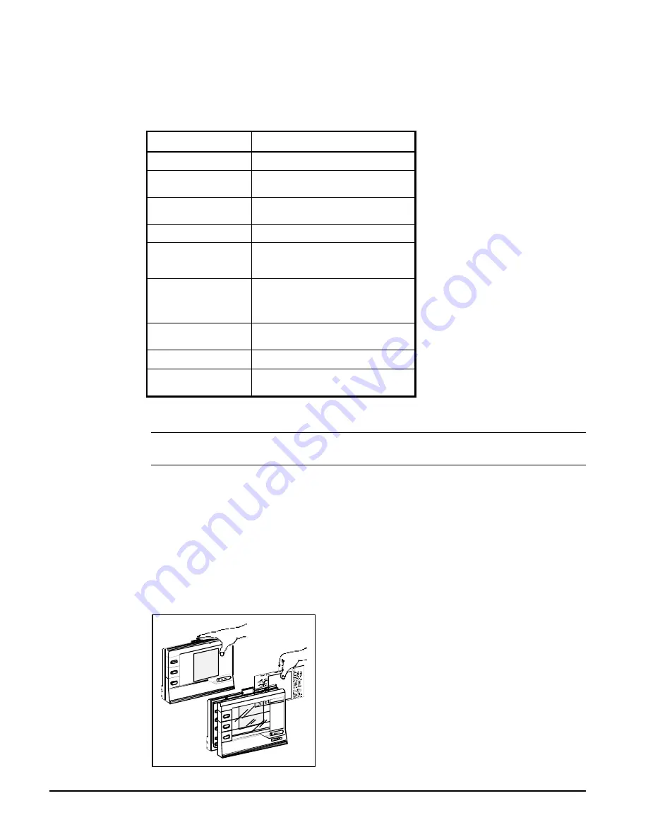
To use the ZT, you'll need the plastic label which is included with your ZT.
Insert
The clear plastic Insert is a custom-made label unique to your chiller. Use this Insert when monitoring
or adjusting specific items of your system:
1.
With the ZT on a flat surface, press the white tab with your index finger (Figure 27).
2.
Pull the front cover of the ZT away from the back and slide the Insert into position.
3.
Press the ZT together. With the Insert in place and the ZT connected, the
l
in the top position of
each display lines up with the first word.
Figure 27, Installing the Insert
Summary of Contents for ACZ 045A
Page 6: ...6 IOMM ACZ AGZ 1 Figure 3 Clearance Requirements...
Page 27: ...IOMM ACZ AGZ 1 27 Figure 12 AGZ AM Single point Connection with FanTrol...
Page 28: ...28 IOMM ACZ AGZ 1 Figure 13 AGZ AM Single point Connection with SpeedTrol...
Page 29: ...IOMM ACZ AGZ 1 29 Figure 14 AGZ AM Unit Control Schematic UNT...
Page 30: ...30 IOMM ACZ AGZ 1 Figure 15 AGZ AM Staging Schematic UNT...
Page 31: ...IOMM ACZ AGZ 1 31 Figure 16 AGZ AM MicroTech Controller Schematic...
Page 32: ...32 IOMM ACZ AGZ 1 Figure 17 AGZ AM Unit Control Schematic MicroTech...
Page 33: ...IOMM ACZ AGZ 1 33 Figure 18 AGZ AM Staging Schematic MicroTech...
Page 34: ...34 IOMM ACZ AGZ 1 Figure 19 ACZ Field Connection Diagram No Capacity Control...
Page 35: ...IOMM ACZ AGZ 1 35 Figure 20 ACZ Field Wiring Diagram Capacity Control Staging...
Page 104: ...Post Office Box 2510 Staunton Virginia 24402 2510 USA 800 432 1342 www mcquay com...


