5.0
SYSTEM SETUP
www.maxcessintl.com
MAGPOWR Spyder-Plus
MI 850A320 1 M
Page 10 of 60
5.1
HARDWARE CONFIGURATION
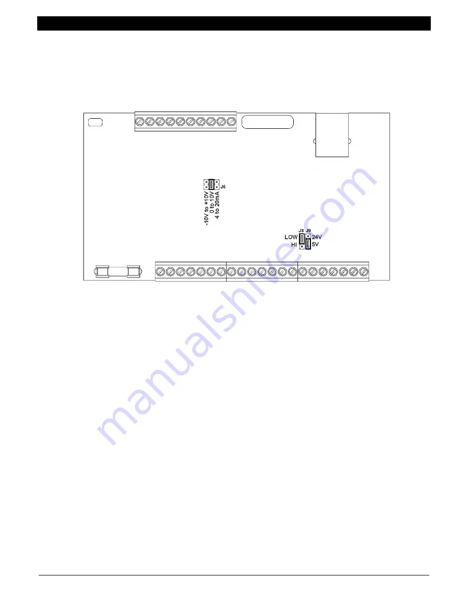
The Spyder has configuration jumpers for:
Control Inputs can be either active high or low,
Control Inputs can be either 5 VDC or 24 VDC logic levels
Main Control Output can be either 0 to 10 VDC, -10 VDC to +10 VDC, or 4 mADC to 20 mADC.
Figure 4. Configuration Jumpers
The Spyder is configured from the factory for 0-10 VDC main output and 5 VDC Logic Low control inputs.
To open the enclosure to provide access to the jumper settings:
1. Open the enclosure by inserting a flat blade screwdriver under the retaining tabs in the base. See Figure 3
2. Lift and rotate the cover being careful not to unplug the keyboard connector.
3. Grasp the display mounting standoffs and pull up while rocking until the shield top is open.
To Close the enclosure after changing the jumper settings:
1. Replace the shield top onto the shield fence. Be careful to keep the display cable wires from being pinched.
2. Replace the cover.
5.2
DIGITAL CONTROL INPUTS
J9 configures the control inputs for either 5V or 24V operation. J8 configures the control inputs for either logic High
or logic Low operation. See Figure 4 for jumper settings. Make sure to configure the software for the selected logic
type. See Section 6.2.2.5 or 7.2.2.7 or 8.2.2.7. The Spyder is configured from the factory for 5 VDC, logic Low
control inputs.
5.2.1
RUN/STOP
Connect TERM.9 to TERM.11 to initiate the stopping function. During STOP TIME the Spyder continues to control
as a closed loop system but STOP MULTIPLIER is also activated. During STOP TIME the output is multiplied by
STOP MULTIPLIER. See Section 9.6.8 for a description of each control type.
5.2.2
E-STOP (E-STOP IS AN AUXILIARY FUNCTION NOT INTENDED TO PROVIDE CATEGORY 1
SAFETY PROTECTION)
Open the connection between Term.10 and Term.11 to initiate E-STOP. On torque device unwinds the output goes
to 100%. On all other systems the output goes to zero. E-STOP overrides Manual mode and Tension Off.
5.2.3
AUTO/MANUAL (Load cell systems and Open Loop Tension systems)
Connect Term.12 to Term.11 to switch to Manual mode. During Manual mode, the main output is directly controlled
by the Manual setpoint analog input (Term.20).


