background image

www.maxcessintl.com 

HEB250 Brake 

MI 850A346 1 B 

Page 14 


Maintenance: 


WARNING 

– Danger of injury from crushing. 

Maintenance and repair tasks on the brake must be performed only when the machine has been stopped 
and has been secured from being turned on again. 


Daily 

– Keep the brake assembly free of dust and debris buildup during shift operation. 


As Needed 

– Keep the rotor free of excessive dust and debris buildup. Use a residue-free brake cleaner such 

as turpentine, acetone, or 

BioBrake

TM

 to wipe down the rotor. 


Fan Replacement 

– Replace fan every three years or 30,000 hours of brake operation. 


Brake Pads 

– Calipers assemblies are designed to prevent brake pads from extending so far that the backing 

plate rubs the rotor. New brake pads measure 15mm [0.591 in] in thickness. Since brake pads will stop 
extending with 6mm [0.236 in] of overall thickness left (half of this is a metal backing plate) it is recommended 
to replace brake pads prior to wearing the brake pads down to the 6mm [0.236 in] thickness. Note: brake pads 
do not contain asbestos. 


WARNING 

– danger to eyes.   

Wear eye protection when working with compressed air. 


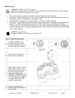
How to replace the brake pads: 

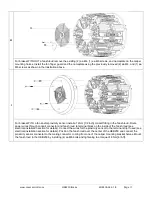
For brakes WITHOUT a fan 
shroud remove the fan finger 
guard. For brakes WITH a fan 
shroud remove the fan shroud. 


Remove (4) bolts to dismount 
each caliper mounting half. 


Brake pads are clipped onto the 
piston and are easily removed. 
Dismount brake pads by prying 
the brake pad away from the 
piston until it has become 
unclipped. To replace with a new 
brake pad simply line up the tabs 
of the brake pad with the tabs of 
the caliper and press until the 
pad has clipped in place. 


Remount caliper mounting 
halves using (4) each previously 
removed bolts. 


Summary of Contents for MAGPOWR HEB250

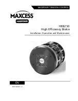
Page 1: ...HEB250 High Efficiency Brake Installation Operation and Maintenance EN MI 850A346 1 B MAGPOWR TENSION CONTROL ...

Page 2: ...d to the rotor is transmitted to a roll of material and acts to create tension in the web being unwound on the roll Introduction HEB pneumatic brake has a 250 mm 10 in diameter rotor Caliper configurations range from 1 to 6 calipers Brake pads come in 3 different coefficients of friction L low M medium and H high Rotor design dissipates heat equally in either direction of rotation i e clockwise or...

Page 3: ... Hole N A N A 01 19 mm 6 x 6 mm M6 x 1 0 8 71 02 20 mm 6 x 6 mm 03 21 mm 6 x 6 mm 04 22 mm 6 x 6 mm 05 23 mm 8 x 7 mm M8 x 1 25 18 159 06 24 mm 8 x 7 mm 07 25 mm 8 x 7 mm 08 26 mm 8 x 7 mm 09 27 mm 8 x 7 mm 10 28 mm 8 x 7 mm 11 29 mm 8 x 7 mm 12 30 mm 8 x 7 mm 13 31 mm 10 x 8 mm M10 x 1 5 35 310 14 32 mm 10 x 8 mm 15 33 mm 10 x 8 mm 16 34 mm 10 x 8 mm 17 35 mm 10 x 8 mm 18 36 mm 10 x 8 mm 19 37 mm...

Page 4: ...500 inch 3 8 x 3 8 inch 3 8 16 UNC 34 300 60 1 13 16 1 8125 inch 1 2 x 1 2 inch 1 2 13 UNC 70 625 61 1 7 8 1 8750 inch 1 2 x 1 2 inch 62 1 15 16 1 9375 inch 1 2 x 1 2 inch 63 2 2 0000 inch 1 2 x 1 2 inch 64 2 1 16 2 0625 inch 1 2 x 1 2 inch 65 2 1 8 2 1250 inch 1 2 x 1 2 inch 66 2 3 16 2 1875 inch 1 2 x 1 2 inch 67 2 1 4 2 2500 inch 1 2 x 1 2 inch 68 2 5 16 2 3125 inch 5 8 x 5 8 inch Serial Number...

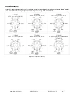
Page 5: ... caliper positions are filled with dummy calipers Views are top views looking at the front calipers 1 Caliper with or w o proximity sensor 2 Calipers with or w o proximity sensor 3 Calipers with or w o proximity sensor 4 Calipers with or w o proximity sensor 5 Calipers with or w o proximity sensor 6 Calipers no proximity sensor available in this configuration Figure 1 Caliper Positioning ...

Page 6: ...www maxcessintl com HEB250 Brake MI 850A346 1 B Page 6 Dimensions Figure 2 HEB250 Dimensions ...

Page 7: ...ns and symbols described in this section are used to avoid possible dangers for users and to prevent material damage SIGNAL WORD Source of danger and its results Avoiding dangers The signal word WARNING refers to the danger of moderate to severe bodily injuries or death The signal word CAUTION refers to the danger of slight to moderate bodily injuries or material damage WARNING CAUTION General dan...

Page 8: ...er in the system The brake must be securely mounted before being placed in operation Only replacement parts obtained from Fife may be used No modifications may be made to the brake Do not place electrical cables under mechanical strain Do not bring this brake into contact with water or other fluids Grease or oil on the internal brake parts will cause a loss of torque Decommissioning The brake must...

Page 9: ... machine frame or mounted to an adapter plate HEB250BKPLT with the correct bolt pattern pre established To mount directly to the machine frame drill and tap 8 ea M8x1 25 holes as shown in figure above Brake assembly was designed for the conduit fitting to be facing downwards in the installed position but can be installed with the conduit fitting facing upwards if desired Doing this will not change...

Page 10: ... between the brake pad and rotor on each side Manually rotate the rotor to verify the rotor does not touch any brake pads during a full rotation E Secure the rotor by tightening the two set screws to the torque listed in the Table 1 Install rotor set screws using LOCTITE 266 high temperature high strength threadlocker or equivalent F Mount the other caliper mounting half to the machine frame using...

Page 11: ...nduit fitting in the fan shroud Route power wires through conduit connector and fan shroud to terminal block on the inside of the fan shroud see electrical installation section for details Connect the wires for the proximity sensor to the terminal strip if used see electrical installation section for details Position the fan shroud over the center of the HEB250 and connect the proximity sensor con...

Page 12: ...ck A The HEB250BKPLT adapter plate is designed to fit the lagerdeckel bearing end plate for Tidland safety chuck sizes 22 30 30 40 and 40 50 Stock chucks use M6 bolts to secure the lagerdeckel to the chuck housing These holes must be re drilled and tapped to M8 or the M8 version of the aforementioned chucks must be ordered Remove the existing 4 ea M6 or M8 countersunk bolts from the lagerdeckel an...

Page 13: ... supply by connecting the positive voltage to the terminal with the red wire and connect the negative voltage to the terminal with the black wire 4 Connect the wires for the proximity sensor to the terminal strip if used The terminal strip connector with the white wire is the positive signal from the proximity sensor and the connector with the black wire is the negative for the proximity sensor 5 ...

Page 14: ...0 591 in in thickness Since brake pads will stop extending with 6mm 0 236 in of overall thickness left half of this is a metal backing plate it is recommended to replace brake pads prior to wearing the brake pads down to the 6mm 0 236 in thickness Note brake pads do not contain asbestos WARNING danger to eyes Wear eye protection when working with compressed air How to replace the brake pads A For ...

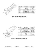
Page 15: ... o rings which will rebuild both the front and back caliper half Model Number RKHEBCAL Replacement Rotor kit Add the appropriate 2 digit bore core from table 1 to the end of the model number Model Number HEB250RTR xx Adapter Plate HEB250BKPLT Exploded views of the caliper assemblies Item Qty Description Part Number 1 1 Front Caliper 712C125 1 2 1 Set Screw 78610 002 3 1 Piston Seal 25A65 1 4 1 Pis...

Page 16: ...2C128 1 8 1 Internal Retaining Ring 28098 059 9 1 Brake Pad Assembly 145C24 X Figure 5 Back Caliper Assembly Exploded View Item Qty Description Part Number 1 1 Proximity Sensor Caliper 712C130 1 2 1 Grommet 93006 064 3 1 Mounting Bracket 706C43 1 4 2 Lock Washer M4 27547 004 5 2 Socket Head Cap Screw M4 27319 005 6 2 Locknut M4 27608 002 7 1 Proximity Sensor with Hex Nuts 32C11 1 8 1 Plug 12C223 4...

Page 17: ... No power to sensor NPN output needs a pull up load to 24 volts Check power supply Check wiring for opens Verify connections Table 1 Troubleshooting Product Specifications WARNING Do not use the devices outside of their rated specifications Temperature Range Operating 0 C to 50 C 32 F to 122 F Storage 30 C to 80 C 22 F to 176 F Relative Humidity 5 to 85 Altitude 0 to 2000 meters 0 to 6562 feet Max...

Page 18: ...ad Low 0 12 Med 0 41 High 0 51 Low 0 12 Med 0 41 High 0 51 1 2 321 36 1007 114 1174 133 338 38 1423 161 1753 198 2 4 641 72 2014 228 2347 265 676 76 2847 322 3506 396 3 6 962 109 3021 341 3521 398 1014 115 4270 482 5259 594 4 8 1282 145 4027 455 4695 530 1352 153 5693 643 7012 792 5 10 1603 181 5034 569 5868 663 1690 191 7117 804 8765 990 6 12 1923 217 6041 683 7042 796 2028 229 8540 965 10 518 1 ...

Page 19: ...and Telefon 49 6195 7002 0 Fax 49 6195 7002 933 Web www maxcess eu Siemensstrasse 13 15 48683 Ahaus Deutschland AMERICAS Tel 1 405 755 1600 Fax 1 405 755 8425 sales maxcessintl com www maxcessintl com EUROPE MIDDLE EAST AND AFRICA Tel 49 6195 7002 0 Fax 49 6195 7002 933 sales maxcess eu www maxcess eu CHINA Tel 86 756 881 9398 Fax 86 756 881 9393 info maxcessintl com cn www maxcessintl com cn INDI...

Reviews: