www.maxcessintl.com
HEB250 Brake
MI 850A346 1 B
Page 2
HEB250 User/Installation Manual
All of the information herein is the exclusive proprietary property of Maxcess International and is disclosed with the
understanding that it will be retained in confidence and will neither be duplicated nor copied in whole or in part nor be
used for any purpose other than for which disclosed.
Copyright 2012, all rights reserved.
Periodically there will be updates to this manual. The latest version is available on our website or by calling the number on
the back of this publication.
These brake devices must not be installed or used in a machine or system which does not comply with the machinery
directive 2006/42/EC.
These brake devices were designed and manufactured to be installed as Partly Completed Machinery into a machine or
partly completed machine.
The instructions must be read and used by all persons who have the responsibility of installing and maintaining these
brake devices.
These instructions must be retained and incorporated in the technical documentation for the machine or partly completed
machinery into which the brake device is installed.
CE Marking:
Only the 2006/42/EC Machinery directive applies to these devices and they are not marked with the CE sign.
Theory of Operation:
Supplied pneumatic pressure acts on a pneumatic seal-piston assembly, which in turn pushes the brake pad against the
rotor to cause frictional torque on the rotor. Torque supplied to the rotor is transmitted to a roll of material and acts to
create tension in the web being unwound on the roll.
Introduction:
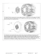
HEB pneumatic brake has a 250 mm [10 in] diameter rotor. Caliper configurations range from 1 to 6 calipers. Brake pads
come in 3 different coefficients of friction; L (low), M (medium), and H (high). Rotor design dissipates heat equally in either
direction of rotation (i.e. clockwise or counterclockwise) simplifying sizing and installation requirements. The brake also
features an anti-squeal design using grooved pads, holes in the rotor face, and a damper situated between the piston and
brake pad. Brake pads feature a snap-in design for easy pad replacement. An optional cooling fan is available. For
measuring roll RPM a proximity sensor measuring 1 pulse per revolution is also available. The brake uses a precision
machined bore and keyway for mounting to the shaft of a machine. Special bore diameters are available as an option.
Model Number Key
The model number and serial numbers are shown on the top of brakes without fan shrouds, and on the side of the shroud
for brakes with a fan shroud.
The model number consists
of the base model “HEB250” followed by 6 digits specifying the options and an additional 2
digits for specials when applicable.
Format: HEB250
–A-B-C-D-EE–FF
A
# of
Calipers
1
1 Caliper
2
2 Calipers
3
3 Calipers
4
4 Calipers
5
5 Calipers
6
6 Calipers
B
Friction Coefficient
L
Low = 0.12
M
Med = 0.41
H
High = 0.51
C
Fan
0
No Fan
F
Fan
D
Proximity Sensor (1)
0
No Proximity Sensor
P
Proximity Sensor
EE
Rotor Bores (2)
00
10mm (pilot hole)
10
28 mm
17
35 mm
32
50 mm
42
60 mm
47
1.000 in
53
1.375 in (1-3/8
in)
FF
Specials (3)
XX
Other bore diameters, etc.

