www.maxcessintl.com
HEB250 Brake
MI 850A346 1 B
Page 13
Electrical Installation
WARNING
– Death or injury can result from electric shocks.
Installation of the fan shroud must be performed when there is no electrical power in the system.
Never place electrical cables under mechanical strain. Always route wiring in either flexible or rigid conduit.
All wiring must comply with the essential requirements of the appropriate standard(s) and is the responsibility of the
installer.
Wiring to the fan shroud must be insulated copper wire with a temperature rating of at least 105
⁰
C [221
⁰F]
. Wire size should
be 0.52 or 0.82 mm
2
(20 or 18 AWG). Tightening torque for the terminals is 0.4 Nm [3.5 lb-in].
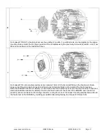
1. Install a 12mm [.500 in] conduit fitting in the fan shroud.
2. Connect the building or machine earth ground to the terminal with the green/yellow wire.
3. Connect a 24 VDC power supply by connecting the positive voltage to the terminal with the red wire and connect the
negative voltage to the terminal with the black wire.
4. Connect the wires for the proximity sensor to the terminal strip if used. The terminal strip connector with the white wire
is the positive signal from the proximity sensor and the connector with the black wire is the negative for the proximity
sensor.
5. Install a pull-up resistor from the proximity sensor signal wire to the +24-volt supply. The resistor should be no more
than 10K ohms and no less than 120 ohms. If the RPM monitor or PLC which the proximity sensor signal is connected to
already contains an internal pull-up, the external pull-up is not necessary. See proximity sensor specifications.
6. Position the fan shroud over the center of the HEB250 and connect the proximity sensor connector to the mating
connector coming from one of the caliper mounting bracket halves.
7. Mount the fan shroud to the HEB250 by installing (4) ea M6 bolts and tightening to a torque of 8 Nm [6 lb-ft].
Figure 3. Electrical Wiring

