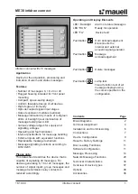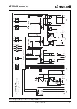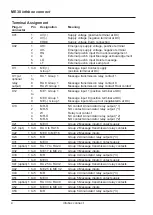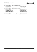
ME30 infobox connect
8
infobox connect
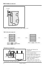
Position of plug connectors X01 and X02 if power supply > 24 V
X02
S01
X01
power supply
> 24 V
- +
2
1
2
1
3
4
5
6
3
X11
X12
RS232 cable pin assignment:
CAN cable pin assignment:
• Strip the cable following the
instructions
• Solder the connection to pin 3 or 8
on the shielding surface
• Connect CAN-L to terminal 4 or 6
Connect CAN-H to terminal 5 or 7
• Terminate the network ends with a
resistor of 120 Ohms between
CAN-L and CAN-H
• At the network end, connect the
shielding to ground (system ground)
2
3
4
6
7
8
1
5
2
3
4
6
7
8
1
5
Socket
Socket
infobox
infobox
infobox
infobox
Modem (Mauell)
PC
1
2
3
4
5
6
7
8
3
4
5
6
7
8
Socket
Plug
infobox
Radio modem
1
2
0 9 8 7 6 5 4 3 2 1
Insulation
Screen
Connecting the CAN cable inside the plug

