background image

Installing & Configuring PhotoPRINT Server 

Configuring the Software 

Sprinter User's Manual 

13-9 


Figure 13-13:  Setup Properties Window – Print Tab 

4.  From the R

ESOLUTION

 drop-down combo box, select 200 or 400dpi as 

required. 


This setting is the only difference between the 200 and 400 dpi resolution. 


5.  From the D

ITHER TYPE

 drop-down combo box, select A

NGLED 

S

CREEN

6. Click S

CREEN

The A

NGLE 

S

CREEN

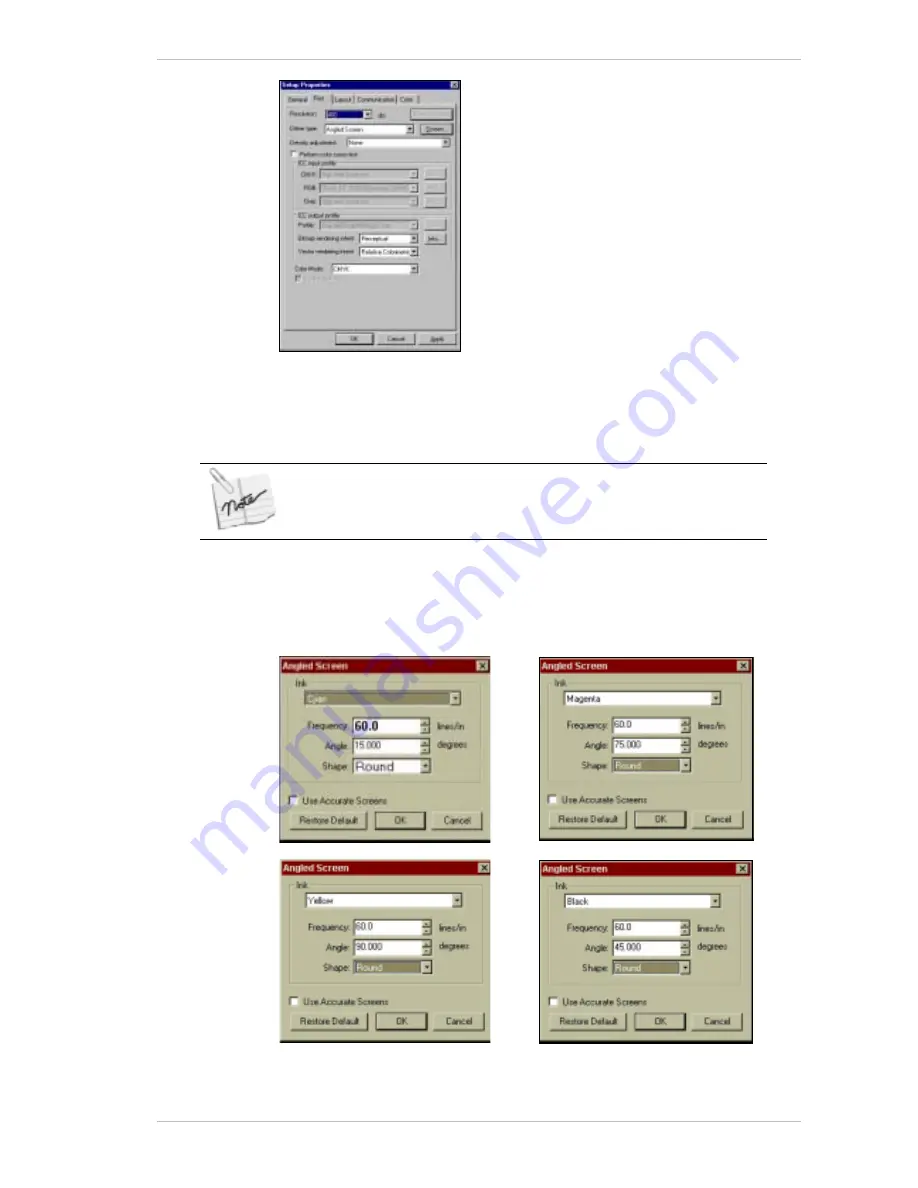
 dialog box appears, with the Cyan settings displayed 

as the default, as illustrated below. 


Figure 13-14:  The Angled Screen Dialog Boxes  


Summary of Contents for The SprinterB

Page 1: ...The SprinterB User s Manual...

Page 2: ...products by unauthorized personnel Environmental Policy Clients are advised that when changing consumables or any part of the printer care should be taken to dispose of these consumables or parts in t...

Page 3: ...r 1 Product shows evidence it has been tampered with or it has been subject to misuse abuse or negligent use or 2 Any repair or alteration of Product was made by someone other than Company including t...

Page 4: ......

Page 5: ...R 3 1 TECHNICAL DESCRIPTION 3 2 THE POWER INLET CONNECTION 3 3 POWER SUPPLY UNITS 3 3 THE THERMAL PRINT HEAD TPH 3 4 TEMPERATURE CONTROL SYSTEM LCS 3 4 THE RIBBON SYSTEM 3 5 THE SUBSTRATE SYSTEM 3 8 T...

Page 6: ...ELF LIFE 4 4 5 INSTALLING THE SOFTWARE 5 1 INSTALLING THE SOFTWARE 5 1 6 AROUND THE WINDOWS 6 1 ABOUT THE SPRINTERB MAIN SCREEN 6 1 THE MENU BAR 6 1 THE TOOL BAR 6 2 THE MAIN SCREEN INFORMATION CENTER...

Page 7: ...OLLECTING SYSTEM 8 12 SOFTWARE PREPARATIONS FOR PRINTING 8 13 USING THE FORWARD ICON 8 13 SETTING THE PRINT HEAD TEMPERATURES 8 13 CONFIGURING THE SPRINTERB PRINTER 8 14 SPECIFYING THE PRINT SETTINGS...

Page 8: ...CEDURES 10 3 RELOCATING THE PRINTER 10 5 LEVELING THE PRINTER 10 6 11 CREATING FILES FOR THE SPRINTERB PRINTER 11 1 CREATING A TIFF BMP FILE IN PHOTOSHOP 11 1 PREPARING A FILE USING SPOT COLORS 11 2 C...

Page 9: ...RE 11 17 12 TEN RULES FOR PRINTING FILES 12 1 FILE FORMAT 12 1 IMAGE SIZE 12 1 COMMON PROBLEMS I TOOLS FOR PACKING VI PACKING THE PRINTER VI FLOW CHART FOR COMPLAINT HANDLING IX ESSENTIAL INFORMATION...

Page 10: ...e 6 9 The Control Dialog Box 6 13 Figure 6 10 The Preferences dialog box 6 15 Figure 7 1 The Update User Service dialog box 7 1 Figure 7 2 A typical User Log File 7 3 Figure 8 1 The Power Socket and A...

Page 11: ...Card removed 9 5 Figure 9 The Print Head Locking Plate 9 6 Figure 9 7 The Configuration Dialog Box 9 7 Figure 9 8 Set of four Power Supply Units 9 9 Figure 9 9 Set of eight Power Supply Units 9 9 Fig...

Page 12: ...re 5 1 The SprinterB Main Screen 5 2 Figure 5 2 The Import File Dialog Box 5 6 Figure 5 3 The Edit Dialog Box 5 7 Figure 5 4 The Gray Level Dialog Box 5 9 Figure 0 5 The Printing Window 5 9 Figure 5 6...

Page 13: ...Set of four Power Supply Units 8 9 Figure 8 9 Set of eight Power Supply Units 8 9 Figure 8 10 Power Supply Resistance Screws 8 10 Figure 9 1 The Air Filter on the Printer 9 1 Figure 9 2 The Scraper 9...

Page 14: ...x The SprinterB User s M Figure 12 18 The PhotoPRINT Server Properties Window 12 12...

Page 15: ...Service Code Chapter 8 Details the preparation for printing Chapter 9 Sets out the procedure for replacing and calibrating the Print Heads Chapter 10 Details the maintenance and scratch prevention pr...

Page 16: ...hat should be typed or a key to be pressed The name of a file or directory 400 TEXT The name of a software screen component or of apart of the Printer SUBSTRATE The description of a procedure To confi...

Page 17: ...ght Any machine parts or components located on the right side of the printer are accessible only after removing the Controls Cover You should use the Around the Windows chapter as your Quick Reference...

Page 18: ...Important Notes Getting Started 1 4 Sprinter User s Manual This page has been intentionally left blank...

Page 19: ...thermal printing Thermal Transfer Printing Alternatively the four Ribbons of the basic YMCK colors can be loaded in the printer between the print head and the substrate The ribbon is thin film mylar...

Page 20: ...Overview 2 2 Sprinter User s Manual This page has been intentionally been left blank...

Page 21: ...hput and easy integration at low operational cost the SprinterB Printer enables you to provide immediate solutions increase flexibility and volume of your large format printing output The SprinterB Pr...

Page 22: ...General View of the Front and Left Side of the Printer Figure 3 2 is the view from the rear right side of the SprinterB Printer Figure 3 2 General View of the Rear Right Side of the Printer Top Cover...

Page 23: ...WER CONNECTOR also supplied that has been connected to the power box by an authorized technician Figure 3 3 The Main Power Connector Power Supply Units The printer has four or eight POWER SUPPLY UNITS...

Page 24: ...e SUBSTRATE Temperature Control System LCS The TEMPERATURE CONTROL SYSTEM LCS maintains the temperature of the PRINT HEADS within a preset range during the printing process The liquid is cooled by the...

Page 25: ...3 5 Figure 3 6 Liquid Coolant pumped to the Aluminum Profiles The Ribbon System The RIBBON SYSTEM as illustrated in Figure 3 7and Figure 3 8 page 3 6 comprises the RIBBON and the RIBBON TAKE UP ROLL...

Page 26: ...th ink which is transferred to the SUBSTRATE The Ribbon Motors and Take up Rolls The RIBBON MOTORS drive the RIBBON TAKE UP ROLLS which collect the used RIBBON The Ribbon Brake The RIBBON BRAKE keeps...

Page 27: ...nt is made by turning the KNURLED THUMB NUT on the brake to between 80 and 90cN m Figure Figure 3 10 Adjusting the Ribbon Brake The Anti static Brush and Strip An ANTI STATIC BRUSH and an ANTI STATIC...

Page 28: ...escription General Description 3 8 Sprinter User s Manual The Substrate System The following figure illustrates the SUBSTRATE path from the SUBSTRATE ROLLER to the COLLECTOR ROLLER Figure 3 12 The Sub...

Page 29: ...that the substrate will not slide but will have tension while turning Figure 3 13 Figure 3 13 The Substrate Roll Holder The Pulling System The PULLING SYSTEM comprises the SUBSTRATE PULLING CYLINDER a...

Page 30: ...material from the SprinterB Printer and collects it into a roll see Figure 3 14 Figure 3 14 The Substrate Collecting System The Pressure Rollers Pistons The PRESSURE ROLLER PISTONS raise and lower th...

Page 31: ...UBSTRATES Figure 3 15 The Optic Sensor When the end of the SUBSTRATE is detected the SUBSTRATE ABSENT window appears Figure 3 16 Figure 3 16 The Substrate Absent Window The printers stops and carries...

Page 32: ...L STATION controls all the operation and printing operations It is located behind the PC DOOR Figure 3 1 page 3 2 Network The SPRINTER PC CONTROL STATION controls all the printer s operations The comp...

Page 33: ...uation To release the EMERGENCY STOP BUTTONS turn the button to the left and push the button next to the CIRCUIT BREAKERS at the MAIN SWITCH BOX Any unprinted file will be saved and will remain on the...

Page 34: ...illustrates the location of the five SAFETY MICRO SWITCHES indicated by white arrows Behind the Rear Cover Behind the Substrate Pass Door Under the Top Cover Under the Front Cover Under the Substrate...

Page 35: ...2 5ft2 hr 60m hr 196 86 feet hr 60 96m 2 hr 656 2ft2 hr Printing Method 4 color process YMCK 3 color process YMC Spot Colors Ink Ribbon length Resin Wax Ribbon 36 40 x 500m Spot Colors 36 40 x 150m Dy...

Page 36: ...0 dpi and 50 dpi for each print head I O card This controls the Pistons and the sensors indicators and is located in the Electronic Box behind the front cover of the printer It also controls all the m...

Page 37: ...000 BTU Hr minimum for SprinterB 40 Liquid Outlet Temp 15 C Liquid Motor cooling liquid anti freeze recommended or water Flow Rate 5 10 GPM LCS location Indoor 3 5m from the printer Connection Requir...

Page 38: ...bbons shelf life is determined by the storage conditions and is summarized in the following table Conditions Resin Ribbon Wax Ribbon Storage Conditions Short term Long term 50 C 85 RH 24HR 20 C 24HR 0...

Page 39: ...CHNICAL SUPPORT The TECHNICAL SUPPORT Page opens 3 Click LOG IN TO THE MEMBERS AREA The LOG IN window appears 4 Enter your username not case sensitive and password you received from your Matan distrib...

Page 40: ...or which you are installing the software and click OK If you have a previous NT setup version already installed on your printer you can move all your preset parameters delay shift etc from the existin...

Page 41: ...nd dialog boxes that you see while working in the application About the SprinterB Main Screen Figure 6 1 The SprinterB Main Screen The Menu Bar The MENU BAR gives you access to different tools and fun...

Page 42: ...Preferences Dialog Box The Warm Up Dialog Box The Cool Down Dialog Box Advance the Substrate Unload Update the Service Code F5 F6 F7 F8 F9 F10 F11 F12 Help Get help About Application Version Number Th...

Page 43: ...enter The lower right hand section of the MAIN SCREEN provides you with current information about the Printer There follows an explanation of each of the two parts of this section Print Information In...

Page 44: ...umn header buttons can be used to sort the entire table in ascending or descending order based on the column selected Column Header Description Image The file name of the selected Image Queue The numb...

Page 45: ...table describes the components contained in the IMPORT FILE dialog box Screen Component Description Look in The directory containing the required files Upper Window Displays a list of files available...

Page 46: ...the number of copies to be printed Horizontal gap Specifies the gap between duplicate images across the width of the substrate Resolution The current resolution of the selected file is displayed by d...

Page 47: ...verlap Y To set the Slice Overlap This overlap can be set to one decimal point for better accuracy From Y To select the first slice to be printed from the Y axis To Y To select the last slice to be pr...

Page 48: ...anual The Gray Level Dialog Box You access the GRAY LEVEL dialog box from the EDIT dialog box The GRAY LEVEL feature gives you basic color management within the image Figure 6 4 The Gray Level Dialog...

Page 49: ...YS while printing through the PRINT command This is called ONLINE HEAD DELAY adjustment Remaining Ribbons and Substrate Graphically and numerically displays the amount of Ribbon and Substrate that cur...

Page 50: ...The Serial Number Font Dialog Box You use the SERIAL NUMBER FONT dialog box to specify the font format of the SERIAL NUMBER but not its color You cannot specify the Serial Number s color from this di...

Page 51: ...n this dialog box as well Figure 6 8 The Configuration Dialog Box You make the following selections from the CONFIGURATION dialog box Group Box Screen Component Description General Configuration When...

Page 52: ...printing General Image Database path Specify the directory path where the files are situated after importing the Image Browse Click this button to browse for the required path Distance between images...

Page 53: ...ist Factory recommended energy levels are 4 8 for paper dye sublimation 18 24 for vinyl resin and 25 30 for banners resin Ribbon type The type of Ribbon used determined by the printing energy level se...

Page 54: ...s Substrate indicates that the Substrate Piston is up indicates that the Substrate Piston is down Yellow Magenta Cyan Black Motor Run Operate and stop the relative Ribbon Take up Motor indicates that...

Page 55: ...oad Click to return the system to rest The head piston will be down the substrate piston will be up The 24V voltage is also closed Test Speed After selecting the Substrate roller speed click this butt...

Page 56: ...this button to browse for an existing Grey Level file General Pressure sensor When activated if there is a change of air pressure greater than 0 5Bar an error message appears informing you of the stat...

Page 57: ...or directly from Matan you will receive a new USER SERVICE CODE in text format txt that has to be copied or selected after browsing and copied into the printer s PC through the UPDATE USER SERVICE COD...

Page 58: ...g the amount that might have remained from before the current update appears in the METERS FEET field of the dialog box The relative totals will decrease according to the quantity used during the prin...

Page 59: ...of the transaction 1 Type of transaction UPDATE USER SERVICE CODE When the user buys from the dealer or directly from Matan 2 The SERVICE CODE 3 The USER PLUG ID 4 The type and width of the ribbon 5 T...

Page 60: ...Viewing Log Files Updating the Software and User Service Code 7 4 Sprinter User s Manual This page has been intentionally left blank...

Page 61: ...SUBSTRATES as well as the RIBBONS Once you have completed the following procedures your SprinterB Printer will be ready to use The Operating Procedures as set out in this manual should be followed in...

Page 62: ...in Screen 6 Switch on the Computer and invoke the program by double clicking the SprinterB icon The MAIN SCREEN appears Figure 8 2 Make sure that the green lights on all HEAD CARDS are lit The HEAD CA...

Page 63: ...Roll Your Sprinter printer has been supplied with the SUBSTRATE installed but not loaded onto the TAKE UP CORE Our technician will load it for you To install a new SUBSTRATE ROLL or replace an existin...

Page 64: ...RUBBER ROLLER the DUST COLLECTOR by pushing it left and pulling it out 4 Wash it under the water tap let it dry for a few minutes and relocate it 5 Remove the LOCKING PIN from both the SUBSTRATE ROLL...

Page 65: ...cut a diagonal piece as illustrated in Figure 8 6 Figure 8 6 Substrate Roll 14 Feed more than a meter of the SUBSTRATE between the SUBSTRATE GUIDING ROLLER and the sprung SCRAPER under the IONIZOR an...

Page 66: ...responding buttons in the Control Panel will indicate Down with a dotted frame around the word 3 Take out the STICKY CLEANING RUBBER ROLLER the DUST COLLECTOR by pushing it left and pulling it out 4 W...

Page 67: ...ning the New substrate to the Existing Piece The preferred method is to ensure that the new Substrate is placed on top of the old Substrate See Figure 8 8 16 Lift the SCRAPER until the join has passed...

Page 68: ...Ribbon 1 From the CONTROL PANEL dialog box click UNLOAD SUBSTRATE The printer will come to rest 2 Open the TOP COVER 3 Tear off the RIBBON on the take up core side close to the core 4 Roll the excess...

Page 69: ...w RIBBON to the empty cardboard roll at three points 12 Close the TOP COVER and from the CONTROL dialog box click the RUN button of the relative RIBBON Ensure that the RIBBON is fed between the ANTI S...

Page 70: ...power on and activate the MOTOR by clicking the RUN button of the relevant color Make sure that the RIBBON is rolling smoothly over the take up core through all its width 14 When the RIBBON has become...

Page 71: ...ystem The Printer can be operated either with or without the SUBSTRATE COLLECTING SYSTEM operating Figure 8 12 The COLLECTING MECHANISM can operate separately from the printer Figure 8 13 Figure 8 12...

Page 72: ...1 Stop the printing process 2 Cut the printed SUBSTRATE from the roll 3 Remove the SUBSTRATE COLLECTING MECHANISM COVER by lifting it slightly and then gently pulling it towards you 4 Pull out both th...

Page 73: ...the SUBSTRATE advancing click OK Setting the Print Head Temperatures During the printing process the PRINT HEADS temperature will naturally increase This increase will be controlled by the settings ma...

Page 74: ...log Box 2 Select the required temperature from the REQUIRED TEMPERATURE spin box 3 Click START to initiate the process Configuring the SprinterB Printer Figure 8 16 The Configuration Dialog Box Use th...

Page 75: ...NFIGURATION dialog box select the appropriate SUBSTRATE The corresponding HEAD settings appear in the HEAD DELAY box within the CONFIGURATION dialog box Adding a New Substrate Type To Add a New Substr...

Page 76: ...nting Heads To select the Active Printing Heads 1 From the MAIN SCREEN click CONFIG or from the UTILITIES menu choose CONFIGURATION The CONFIGURATION dialog box appears Error Reference source not foun...

Page 77: ...after closing the screen by clicking OK Setting the Head Shift To set the Head Shift From the HEADS group box in the CONFIGURATION dialog box set each color s Shift The HEAD SHIFT determines the poin...

Page 78: ...rinted are situated In the IMAGE DATABASE PATH FIELD enter the relevant path or select it by using BROWSE Setting the distance between each printed Image To set the distance between each printed Image...

Page 79: ...e to calibrate the printed length once However if you change to a more elastic substrate such as Banner or Tyvek you should calibrate the printed length accordingly To calibrate the printed length of...

Page 80: ...EDIT dialog box to specify the print settings You must select the required image in the MAIN SCREEN before you begin the editing process Clicking OK will close the EDIT dialog box So you may want to...

Page 81: ...er The Tiling process involves cutting a image vertically horizontally or in both directions so that its printed dimensions match those of the substrate on which it is to be printed or the area where...

Page 82: ...M prevents any color mismatch between slices activating the Flip feature will cause alternate tiles to be rotated 180 This will further help to prevent color mismatching To activate the Flip feature I...

Page 83: ...d in one or more colors you should adjust the NOISE levels of the relative colors The maximum unit value of the Noise adjustment is 30 If you set the noise level too high it will result in the image b...

Page 84: ...the required color s of the SERIAL NUMBER 6 From the FROM drop down combo box enter or select the number of the first serial number you want to appear 7 In the OFFSET X and OFFSET Y fields enter the r...

Page 85: ...uses are displayed at the top of the CONTROL dialog box They are set in the CONFIGURATION dialog box Raising and lowering a specific piston To raise or lower a Color Piston In the CONTROL dialog box c...

Page 86: ...egistration problems The MOTOR S torque must be set according to the diameter of the used COLOR INK ROLL When the roll is empty the torque requirement is low between 4 and 5 and increases as the diame...

Page 87: ...the print mode with the setting specified in the CONFIGURATION dialog box Alternatively when you click PRINT the loading process will automatically be initiated befoe the printing process To unload t...

Page 88: ...icient parameters must be checked immediately after the software installation Use the PREFERENCES dialog box to set your printing preferences Use the PREFERENCES dialog box to specify the unit of meas...

Page 89: ...trols the speed of the MAIN MOTOR Set the MAIN MOTOR COEFFICIENT PARAMETER according to the following table Printer Type Main Motor Coefficient Parameter Sprinter A 1 SprinterB 36 40 5 4 This paramete...

Page 90: ...ource not found The GRAY LEVEL can be adjusted for TIFF files only 50 dpi You can also use the GRAY LEVEL settings that have been saved previously Once you adjust a file s GRAY LEVEL through the EDIT...

Page 91: ...2 Select the required file If the file comprises four separations C M Y or K select one of them and the application will automatically select the others If you have more than one file to import click...

Page 92: ...U of the MAIN SCREEN 2 From the IMAGE menu of the MAIN SCREEN select RENAME 3 The RENAME IMAGE dialog box appears Figure 8 23 4 In the NEW NAME field enter the new name of the file and click OK To ren...

Page 93: ...gure 8 26 The Enqueue Dialog Box To queue a file for printing 1 From the MAIN SCREEN click QUEUE or right click the mouse The ENQUEUE dialog box appears Error Reference source not found 2 Carry out th...

Page 94: ...the PRINT command This is called ONLINE HEAD DELAY adjustment The adjustment will only take effect from the printing of the next file in the queue The new delay value s will be applied to the remaini...

Page 95: ...GURATION and CONTROL dialog boxes 2 From the MAIN SCREEN click PRINT The PRINTING dialog box appears Error Reference source not found The software loads the printer and the printing process commences...

Page 96: ...equipped with five Interlock switches at the following locations For the FRONT COVER For the TOP DOOR COVER For the SUBSTRATE PASS DOOR For the REAR COVER For the SUBSTRATE COLLECTOR ROLLER COVER The...

Page 97: ...also labeled Black cables are ground red and yellow are current and any other colors carry the data The PRINT HEAD is connected to the PRINT HEAD CARD by a number of cables These cables either carry c...

Page 98: ...Figure 9 2 Wiring Between the Head Card and the Print Head Universal If your printer is the SprinterB 40 you should connect the cables according to Figure 9 3 Figure 9 3 Wiring Between the Universal...

Page 99: ...pen the SUBSTRATE PASS DOOR and pass it out through the opening 9 Make sure that all four MOUNTING SCREWS are still in place 10 Carefully remove the new PRINT HEAD from its packaging 11 Check for any...

Page 100: ...hat the PRINT HEAD is touching the metal surface Check that at no point along the PRINT HEAD S length is there a gap between it and the COOLING CHANNEL and that no cables are caught in between 19 Reco...

Page 101: ...done by adjusting the ADJUSTMENT SCREWS and TIGHTENING SCREWS that are located on the upper side of the PRINT HEAD ASSEMBLY Figure 9 5 Before making any adjustments you must loosen the Tighten Screws...

Page 102: ...of the other both on the X and Y axis There is one main direction in which the PRINT HEAD can be moved in order to achieve optimal results with or against the printing direction i e forwards or backwa...

Page 103: ...quarter turn of the ADJUSTMENT SCREW If the quality is worse than it was before you started moving it return the heads to their previous position and move the head in the opposite direction 4 In the C...

Page 104: ...uality of one of the PRINT HEADS is unacceptable move the PRINT HEAD forward or backward exactly half a revolution on each side half a revolution is equal to 4 bits until you obtain the optimal qualit...

Page 105: ...ring printing you have to calibrate the power supply voltage according to the resistance of the heads by turning the screw as indicated in the figure below Some printers have been supplied with four l...

Page 106: ...irstly remove the jumper between contact RC and RCG then carry out the adjustment and relocate the jumper These current changes can influence the heat and the temperature of the heads and consequently...

Page 107: ...ter every month to ensure that the compressed air supplied to the printer is dry Figure 10 1 Power Supply Voltage Screw To drain the Air Filter 1 With the air supply turned on open the drain that is l...

Page 108: ...lean the PRINT HEADS of any deposits of dirt with a paper towel moistened with 100 alcohol 4 Pass a mirror slowly underneath the PRINT HEADS and with the help of a light source such as a strong torch...

Page 109: ...ng substrate loading you must ensure that it is moved away from the SUBSTRATE to allow the SUBSTRATE to pass through You must clean the SCRAPER whenever you clean the DUST COLLECTOR Figure 10 2 The Sc...

Page 110: ...ated from the Configuration dialog box and used at all times This feature allows you to inspect the print heads between each print job and to detect any failure immediately This facilitates your findi...

Page 111: ...et by turning the orange nuts in a clockwise direction so that all four wheels are engaged Figure 10 3 and the printer stands entirely on the four wheels Wheel Engaged Wheel Disengaged Figure 10 3 The...

Page 112: ...the spirit level on the left side panel of the chassis behind the SUBSTRATE PASS door opening At the second leveling point marked B for right side front to rear leveling place a piece of flat metal un...

Page 113: ...n the mode under the file menu and change the file to Bitmap The Bitmap dialog box appears 8 Complete the following parameters Resolution 200 or 400 pixels inch Method Halftone screen 9 Click OK The H...

Page 114: ...ations with the above names even if you chose to RIP only CMY The SprinterB Printer can only print four colors in one pass The above issues can be addressed as follows The simplest way is to make use...

Page 115: ...In most cases you will want to print a file with a rich graphic content photos text colors layout effects etc Using imaging processing software such as Adobe s PhotoShop you can handle photos e g siz...

Page 116: ...Server installed on any kind of Windows operating system and network protocol TCP IP Procedure 1 Create a new AdobePS printer with Matan PPD and download the appropriate driver for your Operating syst...

Page 117: ...terB PrinterPrinting from PC applications DTP to PhotoPrint Server Sprinter User s Manual 11 5 4 Select FILE and click NEXT The SELECT PRINTER MODEL appears 5 From the above windows you have to define...

Page 118: ...MATION window appears 8 Click NO for both options and click NEXT The SetUP INFORMATION window appears 9 Click INSTALL 10 When the installation of the PostScript printer is complete restart your comput...

Page 119: ...he parameters for the printer job settings resolution rendering intent ICC profiles etc In addition you will be able to determine General Settings such as the number of copies print from to and determ...

Page 120: ...utility which allows a connection between MAC and PC Procedure 1 Create a new AdobePS printer icon through the Chooser menu click on the AdobePS icon and select one of the available printers The Adobe...

Page 121: ...1 9 4 Click OK 5 Click Select and a new printer icon appears on the computer desktop 6 Once you ve created the AdobePs printer you can send the jobs directly from the MAC DTP applications to the Photo...

Page 122: ...available in the PhotoPrint Server The option Fonts Inclusion needs to be set to All but fonts in PPD file in the tab PostScript setting as shown below 8 Make sure to select File instead of Printer in...

Page 123: ...rinter User s Manual 11 11 Setting up a PS driver The following process is a typical example of how you would set up a suitable PS driver To set up a PS driver 1 From the CHOOSER window illustrated ab...

Page 124: ...Setting up a PS driver Creating Files for the SprinterB Printer 11 12 Sprinter User s Manual 2 Select SPRINTERB ppd and click SELECT then close the CHOOSER window...

Page 125: ...ld send it to the PS printer To prepare a PS file with FreeHand 1 From the FILE menu select PRINT The following window appears 2 Check the USE PPD option and ensure that SPRINTERB is selected 3 Check...

Page 126: ...rlap objects in the file select the required number of points in the SPREAD SIZE field If not select DEFAULT 11 Open the IMAGING tab 12 In the LABELS MARKS group box select the required options 13 In...

Page 127: ...ars and we recommend you as the FONT INCLUSION option to select All 19 Enter the file name and click SAVE The file is now ready to be sent to RIP Preparing a PS file with Illustrator The following ill...

Page 128: ...the ORIENTATION EMULSION HALFTONE and IMAGE options as required 6 Ensure that all the colors that you have used are checked 7 Click OPEN PPD and from the window that appears illustrated below select...

Page 129: ...Process Black You don t have to make all the colors you are working with spot colors It is only necessary for the ones that you are going to make Over Print The other colors can stay as process color...

Page 130: ...Using Over Print and Trapping commands Creating Files for the SprinterB Printer 11 18 Sprinter User s Manual This page has been intentionally left blank...

Page 131: ...information see the Using Over Print and Trapping Commands section in the Creating a TIFF File in PhotoShop chapter Image Size Because you are dealing with big images and artworks when using the wide...

Page 132: ...Ten Rules for Printing Files 12 2 Sprinter User s Manual This page has been intentionally left blank...

Page 133: ...f your computer If you need to plug a printer into this port plug the PhotoPRINT Server key into the port first Then plug the printer into the key Installing PhotoPRINT Server To install the software...

Page 134: ...nd then PhotoPRINT Server or On your DESKTOP double click the PPS icon The PhotoPRINT ADD SETUP window appears Figure 13 1 2 Click NEXT The ADD SETUP dialog box appears Figure 13 2 Figure 13 2 The Add...

Page 135: ...e Software Sprinter User s Manual 13 3 The PhotoPRINT Server Matan Special Edition main screen appears showing that the 50DPI setup is installed Figure 13 3 The PhotoPRINT Server Matan Special Edition...

Page 136: ...13 4 50dpi already appears in the SETUP NAME text box Figure 13 4 Setup Properties Window General Tab 2 In the MEDIA SIZE drop down combo box select your roll width or as we recommend select 90cm Roll...

Page 137: ...ALIAS option 8 Click the LAYOUT tab The LAYOUT tab appears Figure 13 6 Figure 13 6 Setup Properties Window Layout Tab If you don t want to adjust the print settings of the imported files in a session...

Page 138: ...nel is represented by a slider that increases or decreases the ink density Figure 13 8 Setup Properties Window Color Tab If required edit the values in each box to ensure exact matching between channe...

Page 139: ...he ADD SETUP dialog box appears Figure 13 10 Figure 13 10 The Add Setup Dialog Box 3 In the SETUP NAME text box type 200dpi or 400dpi as required 4 Click FINISH The following window appears 5 Click CA...

Page 140: ...screen double click the 200 or 400dpi icon as specified The SETUP PROPERTIES window appears with the GENERAL tab open Figure 13 12 400dpi already appears in the SETUP NAME text box of this example Fig...

Page 141: ...ION drop down combo box select 200 or 400dpi as required This setting is the only difference between the 200 and 400 dpi resolution 5 From the DITHER TYPE drop down combo box select ANGLED SCREEN 6 Cl...

Page 142: ...required check the PERFORM COLOR CORRECTION option See the section Using Color Management and ICC Profiles page 13 14 9 From the COLOR MODE drop down combo box select CMYK 10 Click the LAYOUT tab The...

Page 143: ...ure 13 17 Setup Properties Window Color Tab 16 If required edit the values in each box to ensure exact matching between channels The settings in the COLOR tab will not show in the job preview ALL allo...

Page 144: ...ith its settings 3 Click OK The selected file appears in the QUEUING window of the MAIN SCREEN Figure 13 11 page 13 8 4 Double click on the file to see a preview If required change the parameters of t...

Page 145: ...ring Intents Perceptual Absolute Colorimetric Relative Colorimetric Saturation Spot Color Importing ICC Profiles PhotoPRINT Server provides as a default some input profiles but no output profiles for...

Page 146: ...a default setting of Generic You also can specify a different CMYK profile by clicking ADD You might for example want to use CMYK SWOP as a profile if you have access to it RGB corresponds to monitor...

Page 147: ...s closely as possible Unlike Relative Colorimetric colors that fall outside the color gamut are included but relocated relative to other colors These two rendering intents Relative and Absolute Colori...

Page 148: ...Using Color Management ICC Profiles in PhotoPRINT ServerInstalling Configuring PhotoPRINT Server 13 16 Sprinter User s Manual This page has been intentionally left blank...

Page 149: ...s Sensor until its LED on the Sensor is lit Manually move the relative piston up and down on the Valve Terminal If this does not work contact your local dealer and request that the Valve Terminal is...

Page 150: ...ion dialog box check the relevant Print Head for printing Check the connections of the SCSI Cable Contact your local dealer to replace the Print Head Card Contact your local dealer to replace the RIP...

Page 151: ...the Substrate Roll Brakes is not adjusted correctly The torque on the Ribbon Brakes is not adjusted correctly The Ribbon Motor torque is too high There is too much used Ribbon on the Ribbon Take up Ro...

Page 152: ...Troubleshooting IV Sprinter User s Manual Adjusting the Substrate Brakes Torque...

Page 153: ...e Reason Solution The HASP Key driver has not been installed Install the HASP Key driver No HASP plug was connected to the parallel port Connect the HASP plug to the parallel port You have inserted th...

Page 154: ...ing arm up Place a sponge between it and the lower roller and bring the arm down Disconnect the system from the power and air supply Disconnect the monitor from its cables Remove the two Allen screws...

Page 155: ...the metal shipping brackets to the printer Place the machine on a palette and using four long screws 14X200mm secure the printer onto the palette Place silica gel inside the printer to prevent humidit...

Page 156: ...Recommended Substrates For the latest details regarding Recommended Substrates visit our web site http www matan co il and from our Home Page click Our Products and click any of the printers displaye...

Page 157: ...he claim if it clearly shows that a particle causing the head damage is encapsulated in the vinyl All claims from particles dust on the surface of the vinyl will be rejected Matan will check the sampl...

Page 158: ...r replacement of substrate ribbon Type of Substrate Type of Ribbon Resin Wax Other Applied Cleaning System None Brush Scrapper Ionizer Other Customer s Remarks ________________________________________...

Reviews: