- 9 -
5. Place the washers back, put on and tighten the
nuts.
6. Screw on the cover of the output terminals
back.
REPLACEMENT OF THE FEED ROLLER
The roller installed at the manufacturer’s place is
suitable for wire diameters of 0.6 - 0.8 mm. In
a thinner/thicker wire is to be used, the roller must
be replaced.
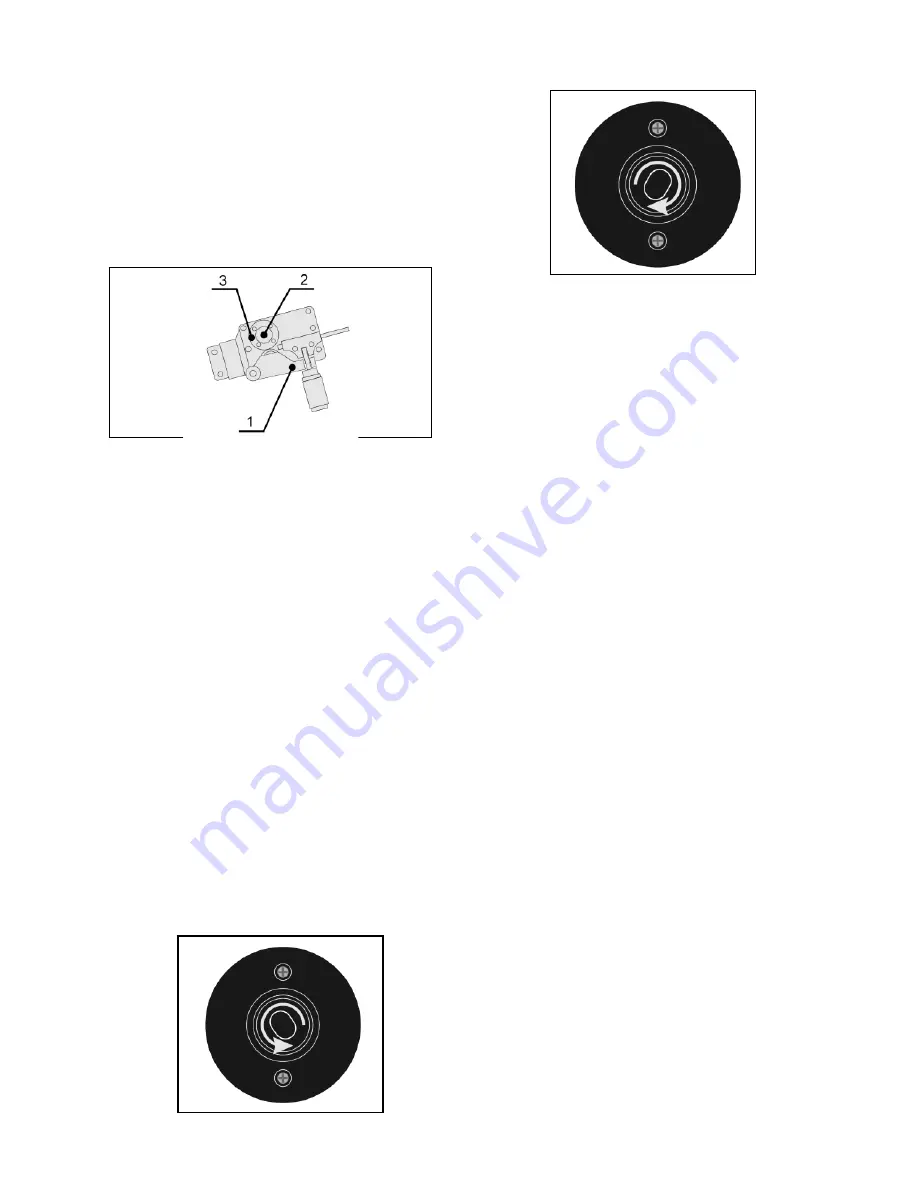
Picture 6
-
Replacement of the feed roller
1. Swing away the pressing arm (Pic. 6, pos. 1).
2. Loosen by hand the grooved screw fixing the
feed roller (pos. 2).
3. Remove the feed roller from its shaft (pos. 3).
4. Turn around or replace the feed roller and fix it
to the original position.
5. Tighten the screw fixing the feed roller.
HOW TO INSTALL THE WIRE REEL
Open the side cover by pressing the plastic locks on
the apparatus. Set the lock of the wire reel carrier
into the “open” position and take the carrier apart.
Place the reel on the wire carrier so that the reel can
turn anticlockwise. Coils containing 5 kg of wire
(Ø200 mm) or 1 kg of wire (Ø100 mm) can be used.
Assemble the carrier again and secure it with the
lock of the wire reel carrier the “locked” position. Do
not forget to install the spring between the carrier
lock and reel adapter. For the wire feed, fix the roller
suitable for the relevant wire type and diameter. (As
the standard, rollers with “V” grooves and 0.6 - 0.8
mm wire diameters are installed).
Slide the reel with the wire on the carrier.
Open
Locked
Picture 7
LEADING-IN THE WIRE
Release the wire end from the reel but keep it
tightly for the whole period.
Straighten the wire end and cut it in a manner
making its leading-in to the wire feed easy.
Open the pressing roller.
Lead in the wire over the lead-in Bowden, feed
roller and torch Bowden.
Hold down the wire so it cannot slip out and
close the pressing roller. Make sure that the
wire is in the feed roller groove.
Set the thrust pressure of the pressing roller to
one half of the scale at the most. If the pressure
is too high, the wire will be deformed and small
shavings created on its surface. If the pressure is
too low, the wire will creep and the feed will not
be smooth.
In order to avoid any injury by pressing a part of the
human body during leading-in the wire into the
feed, close the wire feed cover before pressing the
torch pushbutton.
Press the torch pushbutton and wait until the wire is
moves out of the torch tip.
The wire lead-in rate can be controlled by the con-
trolling element 1 (Pic. 8) on the front panel.
Before welding, apply the separation spray to the
space in the gas nozzle and current drawing die. By
this, the splashed metal particles will not stick to the
surface and the gas nozzle service life will be extend-
ed.
WARNING!
During wire leading-in into the torch, do
not aim the torch against yourself or other persons!
The wire leaving the current tip is very sharp and
may cause injury. Do not place your fingers close to
the feed roller. While the torch pushbutton is
pressed, the roller rotates and can be cause of
squeezing.
IMPORTANT NOTE:
While using the welding appa-
ratus with a backup power supply or a mobile power
source (genset, etc.), it is necessary to use a good-
quality source of a sufficient capacity and good con-
trol system.
Summary of Contents for MW2040
Page 19: ...19 2080...


