- 8 -
NOTE 2:
Owing to the
connected load level, the
approval of the relevant electricity distributing com-
pany may be necessary for the connection of this
equipment to the public mains.
WELDING TORCH
The welding is used for supplying the welding wire,
inert gas and current to the welding place. Once the
torch pushbutton is pressed, the welding wire and
protective gas start to pass through the torch. The
arc is activated at the contact of the welding wire
with the welded material.
IMPORTANT NOTE: If you use a welding wire of
a different diameter than 0.8 mm, it will be neces-
sary to exchange the drawing die on the torch for
a drawing die of suitable diameter.
EARTHING CABLE
Keep the earthing clamp clean so that its contact
with the welded material is complete. If possible,
place them directly to the welded part. The contact
area must be clean and as large as possible. If neces-
sary, the area must be cleaned from paint and rust.
PROTECTIVE GAS AND CYLINDER INSTALLATION
For the protective shield in MIG/MAG welding, use
inert gases (argon, CO
2
, or argon-CO
2
mixture). Make
sure that the pressure-reducing valve is of a suitable
type for the used gas.
Cylinder installation
Fix the gas cylinder properly and in the upright posi-
tion, either in a special holder or trolley. Do not
forget to close the gas cylinder valve after completed
welding.
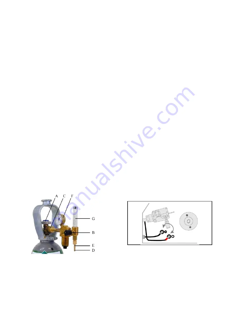
Picture 4
The following installation instructions are applicable
to the majority of pressure-reducing valve types:
1. Keep aside and open for a moment the cylinder
pressure-reducing valve “A” (Pic. 4). Impurities
or dirt, if any, will be blown away from the cyl-
inder valve.
IMPORTANT NOTE: Be careful because of the
high gas pressure!
2. Turn the pressure controlling screw “B” of the
pressure-reducing valve until you feel the spring
compression.
3. Close the pressure-reducing valve.
4. Fit the pressure-reducing valve over the gasket
of the inlet connecting pipe onto the cylinder
and tighten cap nut “C” using a wrench.
5. Fit on the hose adapter “D” with the cap nut “E”
to the gas pipe and fasten with the hose clip.
6. Connect one end of the hose to the pressure-
reducing valve and the second end to the weld-
ing apparatus.
7. Tighten the cap nut with the hose at the pres-
sure-reducing valve.
8. Slowly open the cylinder valve. The cylinder
pressure gauge “F” will indicate the pressure in
the cylinder.
NOTE:
Do not consume the whole cylinder con-
tent. The cylinder should be replaced as soon as
the pressure drops down to 2 bars.
9. Open the valve of the pressure-reducing valve.
10. Press the torch pushbutton, while the apparatus
is switched on.
11. Turn the pressure controlling screw “B” until the
flow-meter “G” shows the required flow rate.
After the completion of the welding operation close
the cylinder valve. If not in service for a longer peri-
od, loosen the pressure controlling screw.
PREPARATIONS FOR WORK - REVERSING THE PO-
LARITY
Some types of the welding wire require in welding
reversed polarity of the welding current. Check the
polarity recommended by the manufacturer indicat-
ed on the wire packaging.
Picture 5 - Reversing the polarity
1. Disconnect the apparatus from the mains.
2. Unscrew the two self-cutting screws fixing the
cover of the output terminals.
3. Loosen and unscrew the nuts fixing the output
cables. Note the correct sequence of the wash-
ers.
4. Swap the cables.
Summary of Contents for MW2040
Page 19: ...19 2080...


