


User’s Manual
L
L
O
O
O
O
P
P
C
C
A
A
L
L
I
I
B
B
R
R
A
A
T
T
O
O
R
R
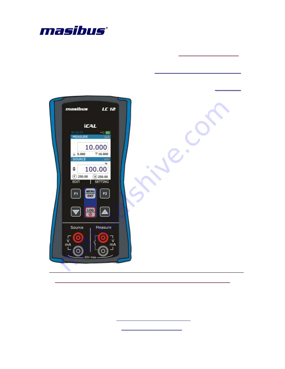
L
L
C
C
-
-
1
1
2
2
Masibus Automation & Instrumentation Pvt. Ltd.
B/30, GIDC Electronics Estate,
Sector-25, Gandhinagar-382044, Gujarat, India
+91 79 23287275-79
+91 79 23287281-82
Email: [email protected]
Web: www.masibus.com
Doc. Ref. no.:mM12/om/101
Issue no. 03


