background image

P a g e

41

 of 

52                                                                                        User Manual


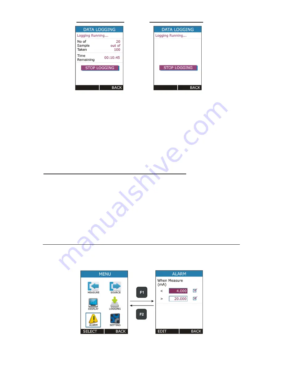
 for Periodic Mode               for Key Press Mode 


For  Periodic  Mode,  this  page  contains  information  of  Number  of 

Samples Taken and  

Time Remaining for Logging in HH:MM:SS. 
 

  Both  Periodic  and  Key  Press  logging  can  be  stop  manually  by 

pressing  F1 key on STOP LOGGING Button. For Periodic Mode, 
Logging will automatically stopped when defined log time ends and 
a message “ 

LOGGING DONE


” pop ups.  


Transferring the Results to a Personal Computer: 
 

A 32-bit Windows® software called 

mCAL+.exe 

is shipped together with 

LC-12 if you bought the Data Logging option. Start this software just as 
any other Windows® software. 
 
All  communication  between  the  PC  and  LC-12  is  initiated  from 

mCAL+.exe

.  

More  information  of  the  software  in  mL12lm101_00.pdf  document 
available in software CD. 


4.5   ALARM Page 


This Page is appears in 

RUN 


MENU 


ALARM. 


Summary of Contents for LC-12

Page 1: ...OR R L LC C 1 12 2 Masibus Automation Instrumentation Pvt Ltd B 30 GIDC Electronics Estate Sector 25 Gandhinagar 382044 Gujarat India 91 79 23287275 79 91 79 23287281 82 Email support masibus com Web...

Page 2: ...perational Sections and Connections 7 2 2 1 The Terminal Connections 8 2 2 2 The KeyPad 12 2 2 3 The Display 13 2 2 4 The USB Connection 13 2 2 5 Stand for Table Top Use 13 2 3 Power Options 14 2 4 Ba...

Page 3: ...ALARM Page 41 4 6 SETTING Page 42 4 6 1 HART Settings 43 4 6 2 Display Settings 43 4 6 3 Date Time Settings 43 4 6 4 Calibration 44 4 6 5 Battery Info 48 4 6 6 Set Password 48 4 6 7 Factory Reset 48 4...

Page 4: ...les representative Under no circumstances may the contents of this manual in part or in whole be transcribed or copied without our permission Trademarks The contents of this manual are subject to chan...

Page 5: ...ry pack To prevent an explosion or fire do not short circuit do not disassemble and keep it safe from damage For operating conditions see section 6 1 on Page 50 To prevent battery leakage or heat gene...

Page 6: ...ntrol for prolonged battery life Measure current mA mA 24V voltage Volt mV Supply current mA mA 2W voltage Volt mV Step Ramp functions Automatic Manual Switch test and condition indicator open closed...

Page 7: ...ation Certificate User Guide 2 Sets of 2mm to 2mm banana cable 2 Sets of 2mm Crocodile clips 2 Sets of connecting plug 4mm to 2mm USB A Male to USB mini B Male cable for PC communication and charging...

Page 8: ...lor Display 4 USB Connection Slot for PC Communication Charging 2 2 1 The Terminal Connections Source Terminals mA Range 0 000 24 000 mA Resolution 0 001 mA mA 2W Range 0 000 24 000 mA Resolution 0 00...

Page 9: ...the current flow The following picture displays the connection for current source for different mode mA Current Source mA 2 Wire Simulation Voltage Generation LC 12 is capable of voltage generation wi...

Page 10: ...wer supply while at the same time measuring the current or simply measuring the current while an external power supply is used The following picture displays the connection for Current Measurement for...

Page 11: ...surement LC 12 is capable of voltage Measurement with two voltage measurement ranges The following picture displays the connection for Voltage Measurement for different mode Switch Test LC 12 is capab...

Page 12: ...s key is use to scroll down to the next parameter And also for decrementing the value of digit in Editbox This key is use to scroll up to the previous parameter And also for incrementing the value of...

Page 13: ...ication Charging the device The USB cable given with the device is USB A type Male to USB B type male It s common for connecting Charger PC 2 2 5 Stand for Table Top Use This Stand would offer the bes...

Page 14: ...ion or fire do not short circuit do not disassemble and keep it safe from damage For operating conditions see section 6 1 on Page 50 To prevent an explosion or fire use only the Masibus specified batt...

Page 15: ...et the best battery duration set a low value for the Backlight Intensity 40 and a short Timeout The maximum operating time without recharging varies depending on the usage and brightness setting of th...

Page 16: ...s off the last set of configuration options stays in memory 3 2 The User Interface Every time LC 12 is switched on the startup message ends in RUN Page There are 4 Display Mode available in RUN Page 1...

Page 17: ...P a g e 17 of 52 User Manual All possible elements are not included in the previous picture but the important ones are discussed in the following chapters...

Page 18: ...ble to Read battery Information 3 Measure Mode Not Working 4 Device unable to get Source Feedback Reading 5 Data Log Memory Corrupt 6 Source Mode Not Working 9 More than one Errors from above list is...

Page 19: ...e Measure Window Input Type The Input Type mA mA Current Input mA 24V mA Current Read Power 24V Input mV mV Voltage Input V V Voltage Input Measure Display Mode The Measure Reading Display Mode Actual...

Page 20: ...rrent 2 Wire Simulation Output mV mV Voltage Output V V Voltage Output Source Display Mode The Source Reading Display Mode Actual Displays the Raw Output Value without any scaling Percentage Displays...

Page 21: ...LAY MEASURE Tare page Actual Value The Raw Input Value without any scaling This will appear only if Main Display in MENU DISPLAY MEASURE is set to PERCENTAGE SCALED Min Displays the minimum value foun...

Page 22: ...ure Source Display Mode on Page 19 Bar Graph Horizontal Bar graph according to Output Percentage Value 0 00 100 00 Percentage Value The Percentage Value in 0 00 100 00 according to Output Value Actual...

Page 23: ...2 4 Display Operations There are mainly four types of widgets available in the Device Menu Style i ListBox ii EditBox iii CheckBox iv RadioButtonBox The below section will show how to change the valu...

Page 24: ...for a parameter To edit the value of an EditBox press F1 key After that EditBox enters into the Edit mode where F1 F2 keys are works as shifter User can shift to desired digit and using UP or DOWN key...

Page 25: ...anging of sign is not allowed But there are few EditBox where these are allowed These types of EditBox are Scaled Low 0 High 100 Range of measure source Alarm Low High value and Editing of Source Valu...

Page 26: ...tonBox is used where very few values can be possible and all the available values need to be visible In this device two types of RadioButtonBox are available One with 1 value can be selectable the oth...

Page 27: ...P a g e 27 of 52 User Manual...

Page 28: ...etc SOURCE Contains Parameters related to Source Mode like Output Type Range Source Type etc DISPLAY Contains Parameters related to different display mode for RUN page LOGGING Contains Parameters rel...

Page 29: ...Range for Measure Input Range Input Range Low 0 to Default Input High This parameter is enabled if Main Display in MENU DISPLAY MEASURE is set to Percentage or Scaled Scaled Input Range Low 0 Scaling...

Page 30: ...his parameter is enabled if Main Display in MENU DISPLAY SOURCE is set to Percentage or Scaled Output Range High 100 High Range for Source Output Range Output Range Low 0 to Default Output High This p...

Page 31: ...Box Ticking this checkbox will enable Step Manual Mode And Un ticking will enable Auto Step Mode Step Time s Enter the time for a single step in seconds Range 1 to 9999 This parameter is enabled only...

Page 32: ...9999 This parameter is enabled only for Auto Step Mode Manual CheckBox is Un Checked Manual Stepping To Enable Manual Stepping select Source Type as STEP Check the Manual CheckBox If this mode is ena...

Page 33: ...ING NOTE While STEP is running STEP settings can t be accessible and Source Page Parameter settings can t be change Stop STEP before changing any settings 4 2 2 RAMP Page Parameter Name Description Op...

Page 34: ...mp Hold 0 icon will appear in Source Display Window according to current RAMP mode in RUN Page and F1 F2 Button change to START SETTING respectively RAMP can be started by Pressing F1 key START After...

Page 35: ...is one RadioButtonBox At a time one or two option can be selected The possible combinations are given below 1 Measure Only 2 Source Only 3 Measure Source 4 Switch Test Source 4 3 1 Measure Display Set...

Page 36: ...which information to be shown in Bottom Left side of the Measure Window on RUN Page Available Options Options Icon Description Reset Reset the Minimum Maximum Max Min Cumulative Avg Value None No info...

Page 37: ...s the Actual Input Value This option is not appear if Main Display is Actual If Measure is not selected as Display mode this parameter will be disabled 4 3 2 Source Display Settings This Page is appea...

Page 38: ...in RUN MENU DISPLAY SWITCH TEST Parameter Name Description Options Mode Switch Test Operation Mode Available Options 2V 24Vdc 30mA Switch Close when External Switch Potential Free Contacts short Swit...

Page 39: ...g Trigger Mode Selection Available Options Key Press Log Data on pressing from RUN key Page Periodic Log Data periodically at every Sampling Rate for total time specified by Logging Time Mode Data Mod...

Page 40: ...start the Logging NOTES Maximum No of Reading that can be stored in Logging Mode Max Reading Periodic 150000 Key Press 572 In Periodic mode changing of any Measure or Source parameter is not allowed...

Page 41: ...ll automatically stopped when defined log time ends and a message LOGGING DONE pop ups Transferring the Results to a Personal Computer A 32 bit Windows software called mCAL exe is shipped together wit...

Page 42: ...put Range Measure Display Mode And also it can t be greater than Alarm High Limit when High Alarm is enabled Alarm High Limit Value Range In accordance with Input Range Measure Display Mode And also i...

Page 43: ...ich display will turn Off To turn the display off press any key Range 0 to 9999 sec Setting 0 will disable this feature That means display will never turn off automatically 4 6 3 Date Time Settings To...

Page 44: ...trument to the manufacturer or an approved service agent for calibration If you use an alternative calibration facility make sure that it uses these standards The unit can be calibrated without openin...

Page 45: ...0 mA ZERO 1 000 mA SPAN 11 000 mA 2 12 000 to 24 000 mA ZERO 13 000 mA SPAN 23 000 mA mV 0 00 to 250 00m V 1 0 00 to 125 00 mV ZERO 15 00 mV SPAN 110 00 mV 2 125 00 mV to 250 00 mV ZERO 140 00 mV SPAN...

Page 46: ...AN Actual Value Edit Box Press MENU ENT key to calibrate the SPAN Follow the same procedure to calibrate for the Sub Range 2 The same procedure is applicable for other Input Type To calibrate input us...

Page 47: ...2 will source 20 000mA Now Measure the source value in Reliable Measure Unit For Example the external measure unit is measuring 20 0100mA Then enter 20 0100 value in SPAN Measured Edit Box Press MENU...

Page 48: ...eters To change password Enter Current Password If the entered password is correct then New Password EditBox will be enabled Then enter the New Password and press MENU ENT key to store it 4 6 7 Factor...

Page 49: ...oose Connections Error Code on status bar One of the peripheral not working properly Solution Restart the Device if still error code showing contact factory Calibration Out Distortion in due to extern...

Page 50: ...mA mV V measurement with 5 backlight on 8 hours for mA generation with 5 backlight on 24V DC 12mA Battery Status Indication Battery symbol displayed with power remaining Operating temperature 00 to 5...

Page 51: ...rce Accuracy Parameter Range Resolution Accuracy mV 0 250 00 mV 0 01 mV 0 02 of reading 2 count V 0 12 00 VDC 0 001 V 0 02 of reading 2 count mA 0 24 00 mA 0 001 mA 0 02 of reading 2 count 6 4 Testing...

Page 52: ...User Manual P a g e 52 of 52 6 5 Enclosure Dimensions...

Reviews: