


BRUSHCUTTER BLADE
WARNING
POTENTIAL HAZARD
・
If the Brushcutter blade is not adequately tightened, it can come
loose from the Brushcutter during use.
WHAT CAN HAPPEN
・
This may cause damage to property or personal injury.
HOW TO AVOID THE HAZARD
・
Make sure the Brushcutter blade is securely fastened to the atta-
ching shaft in the gearcase.
CAUTION
POTENTIAL HAZARD
・
Brushcutter blade is sharp.
WHAT CAN HAPPEN
・
Contact with sharp blade can cause personal injury.
HOW TO AVOID THE HAZARD
・
Wear gloves when you handle the blade.
НІЖ ДЛЯ СТРИЖКИ КУЩІВ
ПОПЕРЕДЖЕННЯ
ПОТЕНЦІЙНА НЕБЕЗПЕКА
・
Якщо ніж для стрижки кущів погано затягнутий, він може
злетіти з кущоріза під час його використання.
МОЖЛИВІ НАСЛІДКИ
・
Це може призвести до пошкодження майна або травми.
ЯК УНИКНУТИ НЕБЕЗПЕКИ
・
Переконайтеся, що ніж для стрижки кущів надійно
прикріплений до кріпильного вала в редукторі.
ЗАСТЕРЕЖЕННЯ
ПОТЕНЦІЙНА НЕБЕЗПЕКА
・
Ніж для стрижки кущів дуже гострий.
МОЖЛИВІ НАСЛІДКИ
・
Контакт із гострим ножем може спричинити травму.
ЯК УНИКНУТИ НЕБЕЗПЕКИ
・
Надягайте рукавички під час роботи з ножем.
РЕЖУЩИЙ ЭЛЕМЕНТ КУСТОРЕЗА
ОСТОРОЖНО
ВОЗМОЖНАЯ ОПАСНОСТЬ
•
Если режущий элемент кустореза недостаточно затянут, он может
ослабнуть и отсоединиться от кустореза во время работы.
ЧТО МОЖЕТ ПРОИЗОЙТИ
• Это может привести к повреждению имущества или травмированию.
КАК ИЗБЕЖАТЬ ОПАСНОСТИ
•
Убедитесь, что режущий элемент кустореза надежно прикреплен к
соединительному валу редуктора.
ВНИМАНИЕ
ВОЗМОЖНАЯ ОПАСНОСТЬ
• Режущий элемент кустореза имеет острые лезвия.
ЧТО МОЖЕТ ПРОИЗОЙТИ
• Прикосновение к острому режущему элементу может привести к
травме.
КАК ИЗБЕЖАТЬ ОПАСНОСТИ
• При работе с режущим элементом пользуйтесь перчатками.
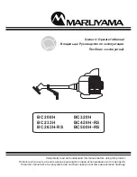
[BC200H, BC233H, BC263H-RS] [#12-1]
1. Remove the blade bolt, the stabilizer and the clamping washer from the
attaching shaft out of the gearcase.
Note: The blade bolt has left-hand thread.
2. Install the brushcutter blade onto the boss adapter, then reinstall the clamping
washer, the stabilizer and the blade bolt.
[BC200H, BC233H, BC263H-RS] [#12-1]
1. Снимите гайку режущего элемента и прижимную шайбу с соединительного вала
и редуктора.
Примечание. Гайка режущего элемента имеет левую резьбу.
2. Установите режущий элемент кустореза на ведущий переходник, затем
установите прижимную шайбу и гайку режущего элемента.
[BC200H, BC233H, BC263H-RS] [#12-1]
1. Зніміть гайку та затискну шайбу ножа з кріпильного вала в редукторі.
Примітка. Гайка ножа має лівосторонню різьбу.
2. Установіть ніж для стрижки кущів на основний перехідник, а потім
установіть на місце затискну шайбу та гайку ножа.
3. Зіставте отвір в основному перехіднику з напрямним жолобом у
редукторі.
Blade Nut
Гайка режущего элемента
Гайка ножа
Brushcutter Blade
Режущий элемент кустореза
Ніж для стрижки кущів
Attaching Shaft
Соединительный вал
Кріпильний вал
Boss Adapter
Ведущий переходник
Основний перехідник
Left-hand thread
Левая резьба
Лівостороння різьба
Gearcase
Редуктор
Редуктор
Clamping Washer
Прижимная шайб
Затискна шайба
3mm hex-wrench
3мм шестигранный ключ-
3мм шестигранний ключ-
Blade Nut
Гайка режущего элемента
Гайка ножа
Brushcutter Blade
Режущий элемент кустореза
Ніж для стрижки кущів
Attaching Shaft
Соединительный вал
Кріпильний вал
Boss Adapter
Ведущий переходник
Основний перехідник
Left-hand thread
Левая резьба
Лівостороння різьба
Gearcase
Редуктор
Редуктор
Stabilizer
Прижимная шайба
Стабілізатор
Blade Bolt
Perno de la cuchilla
Болт ножа
[#12-1]
[#12-2]
[#12-3]
Brushcutter Blade
Режущий элемент кустореза
Ніж для стрижки кущів
Attaching Shaft
Соединительный вал
Кріпильний вал
Boss Adapter
Ведущий переходник
Основний перехідник
Left-hand thread
Левая резьба
Лівостороння різьба
Gearcase
Редуктор
Редуктор
Clamping Washer
Стабилизатор
Затискна шайба
Clamping Washer
Прижимная шайба
Затискна шайба
Stabilizer
Стабилизатор
Стабілізатор
3. Align the hole in the boss adapter with the guide slot in the gearcase.
4. Insert the 3mm hex-wrench into the hole in the boss adapter and the guide slot
in the gearcase to lock the attaching shaft.
5. Tighten the blade bolt.
6. Remove the 3mm hex-wrench from the boss adapter and gearcase.
[BC320H] [#12-2]
1. Remove the blade bolt, the stabilizer and the clamping washer from the
attaching shaft out of the gearcase.
Note: The blade bolt has left-hand thread.
2. Install the brushcutter blade onto the boss adapter, then reinstall the clamping
washer, the stabilizer and the blade bolt.
3. Align the hole in the boss adapter with the guide slot in the gearcase.
4. Insert the Ø3,5mm pin into the hole in the boss adapter and the guide slot
in the gearcase to lock the attaching shaft.
5. Tighten the blade bolt.
6. Remove the Ø3,5mm pin from the boss adapter and gearcase
[BC420H-RS, BC500H-RS] [#12-3]
1. Remove the blade nut, stabilizer and clamping washer from the attaching
shaft out of the gearcase.
Note: The blade nut has left-hand thread.
2. Install the brushcutter blade onto the boss adapter, then reinstall the clamping
washer, stabilizer and blade nut.
3. Align the hole in the boss adapter with the guide hole in the gearcase.
4. Insert the Ø6mm pin into the hole in the boss adapter and the hole in the
gearcase to lock the attaching shaft.
5. Tighten the blade nut.
6. Remove the Ø6mm pin from the boss adapter and gearcase.
3. Выровняйте отверстие в ведущем переходнике с направляющим вырезом в
редукторе.
4. Вставьте 3мм шестигранный ключ- в отверстие ведущего переходника и направляющий
вырез редуктора для блокировки соединительного вала.
5. Затяните болт режущего элемента.
6. Извлеките 3мм шестигранный ключ- из ведущего переходника и редуктора.
[BC320H] [#12-2]
1. Снимите болт режущего элемента, стабилизатор и прижимную шайбу с
соединительного вала и редуктора.
Примечание. Болт режущего элемента имеет левую резьбу.
2. Установите режущий элемент кустореза на ведущий переходник, затем
установите прижимную шайбу стабилизатор и болт режущего элемента.
3. Выровняйте отверстие в ведущем переходнике с направляющим вырезом в
редукторе.
4. Вставьте штифт Ш3,5 мм в отверстие ведущего переходника и направляющий
вырез редуктора для блокировки соединительного вала.
5. Затяните болт режущего элемента.
6. Извлеките штифт Ш3,5 мм из ведущего переходника и редуктора.
[BC420H-RS, BC500H-RS] [#12-3]
1. Снимите Гайка режущего элемента, стабилизатор и прижимную шайбу с
соединительного вала и редуктора. Примечание. Гайка режущего элемента
имеет левую резьбу.
2. Установите режущий элемент кустореза на ведущий переходник, затем
установите прижимную шайбу, стабилизатор и Гайка режущего элемента.
3. Выровняйте отверстие в ведущем переходнике с направляющим отверстие в
редукторе.
4. Вставьте штифт φ6 мм в отверстие ведущего переходника и направляющий
отверстие редуктора для блокировки соединительного вала.
5. Затяните Гайка режущего элемента.
4. Вставте 3мм шестигранний ключ- в отвір в основному перехіднику та
напрямний жолоб у редукторі, щоб зафіксувати кріпильний вал.
5. Затягніть болт ножа.
6. Витягніть 3мм шестигранний ключ- з основного перехідника та редуктора..
[BC320H] [#12-2]
1. Зніміть болт ножа, стабілізатор і затискну шайбу з кріпильного вала в редукторі.
Примітка. Болт ножа має лівосторонню різьбу.
2. Установіть ніж для стрижки кущів на основний перехідник, а потім
установіть на місце затискну шайбу, стабілізатор і болт ножа.
3. Зіставте отвір в основному перехіднику з напрямним жолобом у редукторі.
4. Вставте штифт Ø3,5 мм в отвір в основному перехіднику та напрямний
жолоб у редукторі, щоб зафіксувати кріпильний вал.
5. Затягніть болт ножа.
6. Витягніть штифт Ø3,5 мм з основного перехідника та редуктора.
[BC420H-RS, BC500H-RS] [#12-3]
1. Зніміть гайку ножа, стабілізатор і затискну шайбу з кріпильного вала в редукторі.
Примітка. Гайка ножа має лівосторонню різьбу.
2. Установіть ніж для стрижки кущів на основний перехідник, а потім установіть на
місце затискну шайбу, стабілізатор і гайку ножа.
3. Зіставте отвір в основному перехіднику з напрямним отвором у редукторі.
4. Вставте штифт Ø6 мм в отвір в основному перехіднику та отвір у редукторі, щоб
зафіксувати кріпильний вал.
5. Затягніть гайку ножа.
6. Витягніть штифт Ø6 мм з основного перехідника та редуктора.
[BC200H, BC233H, BC263H-RS]
[BC320H]
[BC420H-RS, BC500H-RS]
Holding Tool
Herramienta de sujeción
Ferramenta de suporte
(
Ø
6mmPin/ Clavija/ Pino)
Holding Tool
Herramienta de sujeción
Ferramenta de suporte
(
Ø
3.5mmPin/ Clavija/ Pino)
<12>
ENGLISH
РУССКИЙ
УКРАЇНСЬКА
Summary of Contents for BC200H
Page 2: ......


