Maruyama BC200H Owner'S Manual Download Page 10

1-2mm 

Play/ Ход 1-2 мм/ Проміжок 1-2 мм

Recessed Hole

Отверстие с выемкой

Втоплений отвір

Lock nut

Контргайка

Контргайка

Cable Lug

Наконечник тросика

Наконечник троса

Slotted fitting    

Разрезная муфта

Жолобчатий фітинг

Carburator bracket

Кронштейн карбюратора

Кронштейн карбюратора

Cable Adjuster Sleeve

Регулировочная муфта тросика

Втулка регулювання троса

Throttle cable 

Тросик дросселя

Паливний трос

Stop switch wires 

Cables del interruptor 

Проводи вимикача

[#8-1]

[#8-2]

[#8-3]

[#8-4]


Thin plastic tube

Тонкая пластиковая трубка
Тонка пластикова трубкаv


Matching connectors

Cоответствующие разъемы
Відповідні з’єднувачі

Thick plastic tube

Отметьте пластиковая трубка
Товста пластикова трубка

Band

Полоса
Хомут

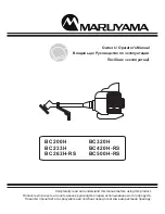
After the connecting the stop switch wires, install the plastic tube as shown.

1. Position the matching connectors on the thin plastic tube.

2. Cover the matching connectors and the thin plastic tube with the thick plastic tube.

3. Bind the thick plastic tube with the band.

4. Then cut out the extra length of the band.

После подключения проводов остановки переключатель, установить пластиковые

трубки, как показано на рисунке.

1. Установите соответствующие разъемы на тонкой пластиковой трубкой.

2. Крышка для разъемов и тонкие пластиковые трубки с толстой пластиковой

    трубки.

3. Привязка толстой пластиковой трубки с полосы.

4. Затем вырежьте дополнительной длины полосы.

Після підключення проводів вимикача встановіть пластикову трубку, як показано на малюнку.

1. Розмістіть відповідним чином з’єднувачі на тонкій пластиковій трубці.

2. Натягніть на відповідні з’єднувачі та тонку пластикову трубку товсту пластикову трубку.

3. Закріпіть товсту пластикову трубку за допомогою хомута.

4. Потім відріжте непотрібну частину хомута.

CONNECTING THROTTLE CABLE AND STOP SWITCH WIRES

1. Insert the throttle cable through the carburetor bracket, then screw a cable adjuster sl

eeve into the carburetor bracket fully. [#8-1]

2. Position the slotted tting on the carburetor so the recessed hole for the lug is away 

from the cable adjuster sleeve.

3. Rotate the carburetor throttle cam and slip the throttle cable through the slot in the slo

tted tting, making sure the cable lug drops into the recessed hole. [#8-2]

4. Operate the throttle trigger a few times to make sure that it works correctly.
5. Adjust the cable adjuster sleeve so the stop on the carburetor throttle cam just contac

ts the throttle stop and the cable position keep 1-2mm play between cable lug and slo
tted fittings when the throttle trigger is fully depressed. [#8-3]

6. When the throttle cable is adjusted correctly, tighten the lock-nut.
7. Plug the stop switch wires into the matching connectors from the engine. Note that 

wire polarity is not important. [#8-4]

ПОДКЛЮЧЕНИЕ ТРОСИКА ДРОССЕЛЯ И ПРОВОДОВ ВЫКЛЮЧ

АТЕЛЯ

1. Вставьте тросик дросселя в кронштейн карбюратора, затем полностью закрутите 

регулировочную муфту тросика в кронштейн карбюратора. [#8-1]

2. Поместите разрезную муфту на карбюратор так, чтобы отверстие с выемкой для 

наконечника находилось с противоположной стороны от регулировочной муфты

тросика. 
3. Поверните кулачок дросселя карбюратора и вставьте тросик дросселя в разрез 

муфты, убедившись, что наконечник тросика попал в отверстие с выемкой. [#8-2]

4. Несколько раз поработайте дроссельным регулятором и убедитесь, что он работ

ает правильно.

5. Отрегулируйте регулировочную муфту тросика так, чтобы упор на кулачке дрос

селя карбюратора коснулся упора дросселя и чтобы при полностью нажатом др
оссельном регуляторе оставалось 1 - 2 мм хода между наконечником тросика и 
разрезной муфтой. [#8-3]

6. Когда тросик дросселя отрегулирован правильно, затяните контргайку.
7. Вставьте провода выключателя в соответствующие соединители от двигателя. 

Полярность проводов не имеет значения. [#8-4]

ПІДКЛЮЧЕННЯ ПАЛИВНОГО ТРОСА ТА ПРОВОДІВ ВИМИКАЧА

1. Протягніть паливний трос крізь кронштейн карбюратора, а потім повністю вкруті

ть втулку регулювання троса в кронштейн карбюратора. [#8-1]

2. Розташуйте жолобчатий фітинг на карбюраторі так, щоб втоплений отвір для нак

онечника знаходився з протилежної сторони від втулки регулювання троса.

3. Поверніть кулачок дросельної заслінки карбюратора та протягніть паливний трос 

крізь жолоб у жолобчатому фітингу так, щоб наконечник троса впав у втоплений 
отвір. [#8-2]

4. Увімкніть дросельний регулятор кілька разів, щоб переконатися, що він працює 

правильно.

5. Відрегулюйте втулку регулювання троса так, щоб вимикач на кулачку дросельної 

заслінки карбюратора лише торкався упору дросельної заслінки та щоб між нако
нечником троса й жолобчатими фітингами була відстань 1–2 мм, коли дросельн
ий регулятор повністю опущений. [#8-3]

6. Відрегулювавши паливний трос, затягніть контргайку.
7. Вставте проводи вимикача у відповідні з’єднувачі у двигуні. Зверніть увагу: поляр

ністьпроводів не має значення. [#8-4]

[BC320H, BC420H-RS, BC500H-RS]

[BC320H, BC420H-RS, BC500H-RS]

[BC320H, BC420H-RS, BC500H-RS]

<8>

ENGLISH

РУССКИЙ

УКРАЇНСЬКА

Summary of Contents for BC200H

Page 1: ...Owner s Operator s Manual Completelty read and understand this manual before using this product BC200H BC233H BC263H RS BC320H BC420H RS BC500H RS...

Page 2: ......

Page 3: ...er safety 5 Fuel safety 5 Brushcutter Grass Trimmer operating safety 5 Symbol explanation 6 Assembly 7 Assmbling Engine and Drive Shaft Assembly 7 Horn Handle Installation 7 Connecting Throttle Cable...

Page 4: ...able 15 Cutting Attachment Guard 16 Brushcutter Blade 18 Shoulder Strap 19 Stop Switch 20 Stop Switch Wires 17 Handle grip 5 Horn Handle 14 Shoulder Harness 1 2 3 4 5 6 7 8 9 10 11 12 13 14 15 16 17 1...

Page 5: ...BC233H BC263H RS BC420H RS BC500H RS BC420H RS BC500H RS SAFETYDECALS ONENGINE Safety Decals are easily visible to the operator and are located near any area of potential danger Replace any decal that...

Page 6: ...ust fumes can cause death 6 Keep the grips clean of oil fuel and dirt 1 2 3 4 5 6 you and others avoid personal injury even death are signal words to identify the level of hazard signals an extreme ha...

Page 7: ...any spilled fuel before starting the engine 6 Move the Brushcutter Grass Trimmer at least 3m away from the fueling location before starting the engine 7 Do not remove the Brushcutter Grass Trimmer fue...

Page 8: ...uel tank with the running or hot engine Do not smoke or place any sources of heat in the vicinity of fuel Breathing exhaust fumes cause death Never start or run the engine inside a closed room or buil...

Page 9: ...f the clamp bracket 2 Insert the left and right horn handles into the clamp bracket Note that the horn handle with the throttle trigger and stop switch goes on the right hand side of the Brushcutter G...

Page 10: ...he slot in the slo tted tting making sure the cable lug drops into the recessed hole 8 2 4 Operate the throttle trigger a few times to make sure that it works correctly 5 Adjust the cable adjuster sle...

Page 11: ...1 Position the matching connectors on the thin plastic tube 2 Cover the matching connectors and the thin plastic tube with the thick plastic tube 3 Bind the thick plastic tube with the band 4 Then cut...

Page 12: ...s shown on 10 2 TRIMMER HEAD GUARD BC320H BC420H RS BC500H RS Install the string cutoff blade and guard extension to the blade guard 1 Insert the square nut into guard extension as shown on 10 3 2 Att...

Page 13: ...from the attaching shaft out of the gearcase keep the stabilizer and blade bolt Note The blade bolt has left hand thread 2 Align the hole in the boss adapter with the guide slot in the gearcase 3 Inse...

Page 14: ...e gearcase to lock the attaching shaft 5 Tighten the blade bolt 6 Remove the 3mm hex wrench from the boss adapter and gearcase BC320H 12 2 1 Remove the blade bolt the stabilizer and the clamping washe...

Page 15: ...Snap the Hook into the ring on the drive shaft To detach the Harness Strap quickly from the Brushcutter Grass Trimmer pull upward on the Red Band Tab WARNING POTENTIAL HAZARD Without the Shoulder Har...

Page 16: ...to expand Never smoke when handling petrol and stay away from an open ame with petrol in an approved container and keep it out of the reach of children Do not mix fuel for more than two month use OIL...

Page 17: ...XTURE CHART Refer to the chart above MIXING INSTRUCTIONS IMPORTANT Never mix petrol and oil directly in the Brushcutter Grass Trimmer fuel tank 1 Always mix fuel and oil in a clean container approved...

Page 18: ...uel tank Flowing fuel should be almost clear not foamy or full of bubbles 2 3 Pull the starter grip without throttle trigger operation T BC200H BC233H BC263H RS BC320H BC420H RS BC500H RS urn the chok...

Page 19: ...e starter grip 3 If the engine fails to start after three to four pulls follow the instructions in the Cold Starting Procedure section above If the engine fails to start after you follow the above pro...

Page 20: ...rasp the throttle lever again IDLE SPEED ADJUSTMENT 18 2 This Brushcutter Grass Trimmer is equipped with non adjustable uel mixture carburetor The idle speed is the only adjustment for the operator WA...

Page 21: ...e idle speed If idle speed adjustment is necessary and after adjustment the cutting attachment rotates or the engine stalls stop using the Brushcutter Grass Trimmer immediately Contact your local auth...

Page 22: ...enly distributed between the arms The cutting attachment should be near and parallel to the ground 5 Accelerate and hold the engine at cutting speed before entering the material to be cut 6 Always rel...

Page 23: ...to the material Forcing the line will cause it to slap against the material increasing line usage and causing poor cutting results 21 2 CUTTING WITH TRIMMER HEAD TRIMMING Hold the bottom of the trimme...

Page 24: ...ng the Brushcutter from right to left Swinging the Brushcutter from left to right can cause the blade to kick back 22 1 22 2 CUTTING BLADES 1 Use only the correct blade MARUYAMA genuine part approved...

Page 25: ...ve the foam element 2 Clean the foam element with warm soapy water Let the element dry completely 3 Apply a light coat of SAE 30 motor oil to the foam element and squeeze out all excess oil 23 1 23 2...

Page 26: ...RS BC500H RS 2 24 1 2 24 2 3 4 5 6 7 25 100 24 3 1 2 3 4 0 6 0 7 5 6 10 7 16 6 Fuel Pick up Hose Wire Cap Holder Fuel Tank Cap Fuel Tank FUEL FILTER The fuel filter should be replaced after every 100...

Page 27: ...er Clean any dirt and debris from the area between the boss adapter and the gearcase Remove the grease plug from the side of the gearcase While rotating the attaching shaft inject lithium base bearing...

Page 28: ...ill provide maximum performance for many many hours if it is maintained properly Good maintenance includes regular checking of all fasteners for correct tightness and cleaning the entire machine STORA...

Page 29: ...ank Primer bulb wasn t pushed enough Engine flooded Off p On Move switch to on position Fill fuel tank Press primer bulb until fuel flows through fuel return line Use warm engine starting procedure En...

Page 30: ...y cm cm cm 500 550 1000 Weight without fuel cutting attachment and strap harness kg kg 4 4 4 5 4 8 6 1 8 4 Cutting equipment Brushcutter Blade Brushcutter Blade optional Trimmer head optional 230 Tip...

Page 31: ...2000 14 EC dB A LWAG EC 2000 14 EC A LWAG 2000 14 EC A Equivalent sound power level LWA measured according to ISO3744 22868 dB A LWA ISO3744 22868 A LWA ISO3744 22868 A 112 110 115 113 Vibration leve...

Page 32: ...apan Name and address of the european authorized representative Obelis European Authorized Representative Center O E A R C Boulevard G n ral Wahis 53 B 1030 Brussels Belgium Tel 32 2 732 59 54 Fax 32...

Reviews: