background image


Installation manual - Eletta

®

 - 29 


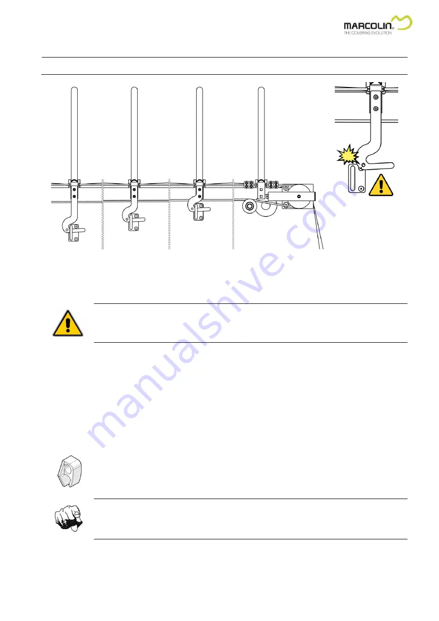
Proceed installing the remaining safety hooks as shown in the figure below: 

Note: 

Before  fastening  the  respective  hooking,  verify  that  while  folding  the  tarpaulin  the  safety  hook  is  fastened  on  a 
different level than the foregoing one, in order not to interfere with the foregoing fastened hooking. 


If  obstacles  interefere  with  the  hookings,  shift  the  hook  upwards  on  the  upper  hole  and  repeat  the  above  described 
fastening operations. 


In the absence of any obstacles while moving the tarpaulin, fasten the U-clamp of the respective hook. 


Proceed with fastening the subsequent hooks. 


WARNING!


We recommend taking care of each U-clamp terminal positioning in order to avoid operating troubles 

while handling the covering system. 


3.9.2 Hermetic closure with elastic strings 

With  this lateral  closure  system,  the  tarpaulin comes  down  a  few  centimetres  from  the upper edge  of  the tipper body and 
then it is tightened by appropriate elastic strings with hooks. 

The tarpaulin borders are equipped with fastening ropes with elastic strings, with plastic or iron hooks. 

For fastening the hooks proceed as follows: 


Move out the tarpaulin and cover entirely the tipper body. 


Fasten the specific hooks using the supplied rivets on the hooking points in the bottom part of the tipper body. 


Make sure that the fixing height of the hooks permits a proper tightening of the elastic strings. 


INSTRUCTION!


During the training course REPEAT often to the operator that HE HAS NOT TO MOVE THE VEHICLE 

while the elastic strings are still loose. 


Summary of Contents for Eletta

Page 1: ... COVERING SYSTEM FOR TIPPER TRUCKS Installation Manual English Translation of the original instructions in Italian language ...

Page 2: ...r l reserves the right to make changes at any time without notice All mentioned product names and trademarks are exclusively owned by the respective holder Marcolin Covering s r l took great care in editing this manual however the company denies liability for errors and omissions if present and for personal and animal injuries as well as for material and environmental damages as a consequence of t...

Page 3: ...cable 19 3 4 5 Steel cables tightening up 20 3 5 Installation of the protective casings electric version 21 3 6 Installation of the protective casings hand operated version 23 3 7 Fastening of the operating rod hand operated covering system 25 3 8 Tarpaulin fastening 26 3 9 Lateral hooking system for the covering 27 3 9 1 Standard closure with automatic L hooking system 27 3 9 2 Hermetic closure w...

Page 4: ...tomer s covering system45 5 4 1 General tightening up of the screw connections 45 5 4 2 Checking of the conservation status of metal structure and bows 45 5 4 3 Checking of the tarpaulin conservation status 45 5 4 4 Checking of the elastic strings or the automatic safety hooks only if installed 45 5 4 5 Checking of the contact plates only if installed 45 5 4 6 Checking of the sliding conditions of...

Page 5: ...other documentation received by Marcolin Covering s r l together with the covering system to the end user 1 2 1 The teaching and training course for the end user must include the following items The end user has to be informed about the great importance of the following operations recognizing its own machine knowing well the piece parts the machine is made of and their specific function and applic...

Page 6: ...efore installing the covering system it is essential to know well its characteristics and the various elements the system is made of The figure below shows the main parts making up the system 1 Front covering driving system hand or motor operated 2 Rear cable tensioning system 3 Tarpaulin of variable size according to tipper body length 4 Covering fastening system depending on the model it could b...

Page 7: ...ement of whatever is usually called spare part is not regarded as a modification 2 3 Tipper body construction features for a good installation Before installing the covering system check following items The linearity of all the upper edge of the tipper body The accuracy of flatness between the installation area of the covering protrusion on the front side of the tipper body usually called cab guar...

Page 8: ...ce for avoiding to be an obstacle for hinges WARNING A wrong positioning of the tension plate could cause damages for the covering or for the tipper body If in doubt carry out mobility trials of the rear mobile elements to avoid unpleasant surprises Drill four M10 threaded holes on the side corresponding to the holes on the plate at the distances shown in the figure above Fasten the plate using th...

Page 9: ...art to the tipper body allowing this way an easy maintenance in case of accidental breakage In this manual reference will be made to standard assembly of the covering system 3 2 2 Processing and preparation of the cab guard Drill the holes Ø 9 of the fixing seats according to the dimensions shown in the following drawings Right view Superior view right side Superior view MR seat Superior view left...

Page 10: ...on the side to the correct fastening it can be made also with the seats positioned on the upper rear part holes for hexagonal head screws B or upper front hole C Proceed fastening the element to the cab guard using the screws washers and self locking nuts supplied or alternatively if the thickness allows it threaded M8 and tighten the screws making sure to insert suitable thread locker Note In thi...

Page 11: ...r and the transmission shaft preassembled in the same unit 1 CC motor 2 Gear unit with pin for emergency operation 3 Central support plate 4 Drive shaft Place the motor unit on top of the cab protection WARNING make sure there is a 3 mm space from the edge of the cab guard Fasten the unit with the screws washers and nuts supplied using an appropriate threadlocker see par 3 2 3 ...

Page 12: ...300 mm This makes it possible to cover bodies having a width of 2100 to 2700 mm without any further intervention by the installer Mount the first shaft coupling the joint of its fixed end to the output shaft of the reducer Lock the coupling with the hex screws and the self locking nut supplied Extend the shaft Attach the other end to the lateral drive unit using the pin supplied Mount the other te...

Page 13: ...h respect to the direction of travel of the vehicle of the cab guard it is in fact more accessible for the driver leaving the vehicle In this manual reference will be made to standard assembly of the covering system on the left side referring to the direction of travel For the installation on the opposite side it will be sufficient to perform the operations mirrored on the opposite side being care...

Page 14: ...ion unit Position the unit as in figure by joining the support plate to the side of the cab guard of the vehicle and adjacent to the front part The unit is fastened laterally with 2 countersunk screws A and nuts However if there are impediments on the side to the correct fastening it can be made also with the seats positioned on the upper rear part holes for hexagonal head screws B or upper front ...

Page 15: ...unk screws A and nut D and on the upper rear part with hexagonal head screws B and nuts C 3 3 4 Telescoping shafts installation In order to adapt to all types of tipping trailers semi trailers or roll off bodies the Eletta cover is equipped with two telescoping drive shafts that greatly reduce installation time Each shaft can be extended by 260 mm This makes it possible to cover bodies having a wi...

Page 16: ...work of the first setting it within the desired length Max 260 mm Attach the other side of the second shaft on the side transmission unit with the cylindrical plug Drill holes Ø 6 for the seats of the shafts and secure with the two dowel pins supplied Final result of the operation ...

Page 17: ...paulin in case of hand operated version and the lesser the motor effort in case of electrically operated version Loosen the rear tensioning plates Loose the centrally arranged screw that fixes in place the guide pulley 1 Undo the screw adjusting the running of the guide pulley slide 2 Shift the pulley towards the front part 3 4 1 Positioning of the covering tarpaulin The covering is supplied compl...

Page 18: ...hrough the bushings on all the feet and leave 10 15 cm length of rope out of the last one Note Pay close attention while fixing the pulling bow because a misalignment could compromise the covering workings Now proceed with the lower end of the steel cable Lead the lower end of the wire rope to the back of the body Wind the rope around the rear transmission pulley 1 Lead the end of the wire rope ba...

Page 19: ...e of the plate 4 Before tightening the clamp 5 pull the cable manually for tensioning it 5 Loose the first fastened clamp 3 and refasten it holding both cables 6 For greater safety it is mandatory to fasten one additional clamp on the left 2 and right 6 of the previously fastened ones WARNING IT IS FORBIDDEN TO use different materials than those supplied with the system The cables must be secured ...

Page 20: ...up the steel cable WARNING The left and right hand ropes must be given the same amount of tensioning The drive pulley is designed with a V shaped groove to prevent slipping and therefore does not require excessive tensioning When the required tension is achieved block the guide pulley tightening the central screw 1 Repeat the operation on the opposite guide pulley WARNING During the installing act...

Page 21: ...he casings have the same shape and size and fasten it to the lateral drive unit with the screws supplied placing one at the bottom of the casing and two on the sides Place the left protection casing on the support of the drive pulley of the left side transmission group If too long on the redactor side cut to size Place the left protection casing on the support of the drive pulley of the right side...

Page 22: ...in figure drill 2 holes Ø9 at the slotted holes of shafts casings fasten the central casing to the shafts casing using the screws and locknuts supplied 1 2 Fasten then all casings on the front of the cab guard using the screws washers and nuts supplied Final result of the operation ...

Page 23: ...ard depending on the placement of the manual transmission and screw it to the lateral drive unit with the supplied screws one at the bottom of the casing and the other laterally Insert the second gear protective casing on the opposite side to the previous one and screw the lateral drive unit with the appropriate screws supplied one in the bottom of the casing and the other laterally Place the left...

Page 24: ...en the central protection casing on the two casings of the drive shafts if too long cut them to size and drill again Ø8 with the appropriate countersunk screws washers and nuts supplied Fasten then all casings on the front of the cab guard using the screws washers and nuts supplied Final result of the operation ...

Page 25: ...he extension piece 2 with the supplied screws 3 and self locking nuts 4 Note During its working life the structure is subject to vibrations and stress therefore it is recommended to apply a threadlocker Loctite liquid Place and fasten the operating rod on the pivot 5 of the manual transmission group with the supplied screws 3 and self locking nuts 4 provided Fasten the holder for the rod Find a su...

Page 26: ...ntion while fastening the tarpaulin in case of automatic rear closing In such circumstances refer to the process described in the specific paragraph 4 1 Move the tarpaulin and cover the tipper body stopping the pulling bow 70 mm before the rear pulley The tarpaulin has to be moved according to the installed driving system type manually or electrically operated Tighten and fasten the PE band 3 on t...

Page 27: ...the vehicle is ready for moving on the road For installing proceed as follows Move the covering and cover the tipper body entirely Define the fastening positions of the safety hooks For fastening the covering 2 or 3 safety hooks supplied in different heights are planned to be evenly distributed along the side of the tipper body The number of safety hooks is in any case not binding as it can change...

Page 28: ...ows Place the U bolt centrally to the safety hook Drill the board wall of the tipper body and fasten the hooking with suitable supplied rivets Now the positioning of the remaining safety hooks can be done WARNING From now on the height positioning of the safety hook is the decisive factor for a proper working of the covering system YES ...

Page 29: ...itioning in order to avoid operating troubles while handling the covering system 3 9 2 Hermetic closure with elastic strings With this lateral closure system the tarpaulin comes down a few centimetres from the upper edge of the tipper body and then it is tightened by appropriate elastic strings with hooks The tarpaulin borders are equipped with fastening ropes with elastic strings with plastic or ...

Page 30: ...r trailer connection zone to the Motor Control Unit power supply 2 50 m Connection to Motor Control Unit terminals Yellow Yellow C Open ended for cutting to length to connect to contact plate Connection from Motor Control Unit motor output to contact plate 4 50 m Connection to contact plate terminals D Open ended for cutting to length for connection to the motor Connection from contact plate to mo...

Page 31: ... MINI TRANSMITTER 3 10 2 Installation of the electrical components Hereafter the required operations for installing the electrical components Using proper hooking elements fasten the Motor Control Unit on the chassis of the tipper body Fasten one of the two contact plates on the front part of the tipper body Fasten the other contact plate on the chassis IMPORTANT The fastening of the contact plate...

Page 32: ...ate Connect the motor to the movable contact plate Note Make sure that cables are firmly fastened to the tipper body in order that they would not form an obstacle or cause an entanglement risk Note The connection of the motor polarities determines the correspondence between the switching command and the related function 3 11 Switch panel of the machine 3 11 1 Description of the Motor Control Unit ...

Page 33: ...lity 3 11 3 Control switches of the Motor Control Unit for operators UNCOVERED switch COVERED switch Emergency mushroom pushbutton with safety lock 3 11 4 Description of the radio control system The radio remote control consists of a pocket remote control to be used also as a key fob Below the available switches 1 UNCOVERED switch 2 COVERED switch ORDINANCE The remote control MUST BE KEPT AND USED...

Page 34: ...nts to fasten the tarpaulin for the transport way if provided for the version installed on the vehicle Press the emergency mushroom pushbutton and remove the key Carry out a quick but attentive control especially of the automatic hooks to verify that everything is in good order before moving the vehicle on the road 3 11 6 Interruption of machine operations For stopping the covering moving release ...

Page 35: ...rol Unit is equipped with an automatic motor shut down when covering reaches the end stop Carry out a quick but attentive control to verify that everything is in good order before starting the tilting movement of the tipper body 3 11 11 How do I interrupt the machine operations Follow the process described in paragraph 3 11 6 3 11 12 How do I stop the machine in case of emergency Follow the proces...

Page 36: ...y qualified personnel to avoid invalidation of warranty By using a suitable screwdriver loosen the screws at the corners of the Motor Control Unit cover Remove the cover taking care not to damage the existing seal Replace the blown fuse Close again the Motor Control Unit with its cover taking care not to damage the existing seal 3 12 2 Motor unlocking in emergency situation WARNING Prior to perfor...

Page 37: ...mpletely closed Tighten up and fasten the PE flat strip 3 on the superoir lateral casing Tighten up the front part of the tarpaulin Fasten the tarpaulin and the PE flat strip 3 on the top of the tipper body using the specific clamping plate 2 and rivets 1 Cut the excess tarpaulin part off Now it is possible to set up the automatic rear closing system in order that while closing the tarpaulin manua...

Page 38: ...counterplate with adjustable stroke for the pulling double support Clamp screws and self locking nuts for fastening the plates For installing proceed as follows FINAL RESULT OF THE OPERATION 1 Remove the screws and the self locking nuts from the external bow support of the double pulling bow 2 2 Position and fasten the support plate 1 on the pulling bow support 2 with the supplied screws 3A and 3B...

Page 39: ...g the installation position in order to avoid to form any obstacle for mobile elements as the tailgate The best position for the plate is the one as close as possible to the rear board but at a sufficient distance for avoiding to be an obstacle for hinges WARNING A wrong positioning of the tension plate could be cause of damages for the covering or for the tipper body In case of any doubt we recom...

Page 40: ...cular to the board walls in order to avoid any later readjustments The quick cable release system is equipped with a lever for opening and closing the release system To release the cables operate in this way insert the lever 2 in the central hole of the release device open the release device turning the lever in the direction shown in the figure A remove the locking pin 1 from the pivot of the pla...

Page 41: ...ng to the length of the tipper body or the customer s requirements Nota The positioning of the wheel hooks is essential for the proper working of the hooking system Fasten the wheel 1 on its support 2 with the supplied screw 4 and self locking nut 5 Lean the wheel hook support 2 against the lateral side of the bow support Fasten the wheel hook support with the supplied screws 7 and nuts 6 Note App...

Page 42: ...ook upwards on the upper hole and repeat the above described fixing operations In the absence of any obstacles while moving the tarpaulin fix the lower support of the respective rolling hook Proceed fastening the subsequent wheel hooks WARNING We recommend taking care of each rolling hook positioning in order to avoid operating troubles while handling the covering system ...

Page 43: ...al space of the tipper body is required Make sure that the internal space is empty and clean to avoid any sliding and falling Wear suitable protective clothing DO NOT WALK ON THE TARPAULIN The manufacturer denies any liability Inside the tipper body remove the cable plastic ties which fasten the tarpaulin to the bow support Undo the self tapping screws which fasten the bow to its support Carry out...

Page 44: ... the frontside of the tipper body remove the aluminium flat bar which fastens the tarpaulin Inside the tipper body remove the cable ties which fasten the tarpaulin to the bows Remove the damaged tarpaulin Proceed to position the new tarpaulin Inside the tipper body fasten the tarpaulin to the various bows by using common cable ties for standard PVC tarpaulins CAUTION For fire resisting PVC tarpaul...

Page 45: ...ify especially the wear and tear status of the most stressed parts like the frontal fastening and the lateral fastening of the bows 5 4 4 Checking of the elastic strings or the automatic safety hooks only if installed Verify the conservation status of the hooking components if necessary provide for their replacement 5 4 5 Checking of the contact plates only if installed Check the conservation stat...

Page 46: ...E SHAFTS Make use of lithium based grease After greasing reposition the protective casings WARNING It is forbidden to handle the machine without repositioning the protective casing The manufacturer denies all liability 5 4 10 Filling the machine control register The manual handed over to the customer includes a chapter referred to as Control register The Control register MUST ALWAYS BE fulfilled c...

Page 47: ...by using the remote control Power supply voltage reversal Check that the positive pole of the battery is connected to the RED terminal of the Motor Control Unit and that the negative pole is connected to the BLACK terminal of the Motor Control Unit The Motor Control Unit seems to be functioning the internal relay can be heard but the motor does not run Possible oxidation of the electrical contacts...

Page 48: ...48 Installation manual Eletta C Ch ha ap pt te er r 6 6 ENCLOSURES 6 1 Reference diagram for electrical connections ...

Reviews: