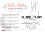
background image

8

solutions creator

TC 322 - TC328

3

ITALIANO

ENGLISH

  DESCRIZIONE DELLA MACCHINA

con illustrazione delle parti componenti rilevanti ai fi ni 
dell’uso.

PEDALIERA (fi g.1) (1)

Comprende i pedali di comando della macchina:
• Il pedale comando invertitore (1-A), per far ruotare il 
piatto autocentrante nel senso desiderato.
• Il pedale comando stallonatore (1-B) per azionare  il 
bracciostallonatore (2-F).
• Il pedale comando apertura e chiusura (1-C) per aprire e 
chiudere le griffe dell’autocentrante (4-P).

STALLONATORE (fi g.1) (2)

Lo Stallonatore è il dispositivo per stallonare il pneumati-
co dal cerchio esi compone di:
• Braccio Stallonatore (2-F) azionato pneumaticamente da 
un cilindroa doppio effetto.
• Paletta (2-E) per lo stallonamento del pneumatico.
• Appoggi antiabrasivi (2-G) per l’appoggio del cerchio 
durante lafase di stallonamento.

GRUPPO PALO (Fig.1) (3)

Il Gruppo Palo è composto da un Palo fi sso che supporta 
i componentinecessari per smontare  il pneumatico dal 
cerchio (e per rimontarlo):
• Il Braccio mobile a bandiera (3-H) per il posizionamento 
dellaTorretta.
• Il Volantino (3M) per la regolazione della posizione oriz-
zontale delbraccio.
• La  Leva di bloccaggio (3-L) per la regolazione della 
posizioneverticale dell’asta.
• La Torretta (3-I) per togliere (e rimontare) il  pneuma-
tico dal cerchiocon l’ausilio della leva alzatalloni (vedere 
accessori in dotazione).
• Il Rullino di scorrimento (3-N), inserito nella linguetta 
della torretta, permette di operare sui pneumatici senza 
rovinare cerchio e tallone.

AUTOCENTRANTE (Fig.1) (4)

L’autocentrante è il dispositivo per il bloccaggio e la rota-
zione del cerchio; è azionato pneumaticamente da 2 cilin-
dri “autocentranti” ed è composto da:
• 4 corsie mobili (4-P) con cunei di bloccaggio (4-O) per 
il bloccaggio interno od esterno del cerchio;
• un piatto autocentrante (4-Q) per ruotare il cerchio nei 
due sensisenza sbloccarlo.

  DESCRIPTION OF THE MACHINE

with illustrations of the component parts relevant for 
use.

PEDAL CONTROLS (fi g. 1)(1)

The machine control pedals include:
• Invertor control pedal (1-A) for rotation the chuck plate 
in the direction desired.
• Bead breaking control pedal (1-B) to activate the bead 
breakingarm (2-F).
• Open and close control pedal (1-C) for opening and clo-
sing the chuck jaws (4-P).

BEAD BREAKER (fi g. 1) (2)

The bead breaker is a mechanism for unbeading tyres from 
rims and iscomposed of:
• Bead breaking arm (2-F) activated pneumatically by a 
double actioncylinder.
• Plate (2-E) for tyre bead breaking.
• Anti-abrasion supports (2-G) for support during the 
bead breakingphase.

COLUMN UNIT (Fig.1) (3)

The column unit is composed of a fi xed column   which 
can be tilted backand which carries the components ne-
cessary for unmoun-ting the tyre from the rim (and for 
re-mounting):
• The swinging arm (3-H) for positioning the head.
• The handwheel (3M) for the adjustment of the horizon-
tal position of the arm.
• Locking lever (3-L) for regulating the vertical position 
of the rod.
• The head (3-I) for removing (and refi tting) the tyre from 
the rim with the help of the bead lifting lever (see acces-
sories provided).
• The sliding roller (3-N), inserted inside the tongue of 
the head, avoids any damage to the rim or bead.

SELF-CENTERING CHUCK (Fig.1) (4)

The chuck is the device for locking and rotating the rim. It 
is driven pneumatically two “self-centring” cylinders and 
is composed of:
• 4 slide tracks (4-P) with 4 locking wedges (4-O) for the 
internal and external locking of the rim. 
• A self-centring plate (4-Q) for rotating the rim in both 
directions  with-out unlocking it.

M

L

H

I

N

4

O

P

Q

1

C

B
A

2

F
E

G

 LEGENDA

1• PEDALIERA

A: Pedale Invertitore
B: Pedale Stallonatore
C: Ped. Apertura e Chiusura

2• STALLONATORE

E: Paletta Stallonatore
F: Braccio Stallonatore
G: Appoggi antiabrasivi

3• PALO

H: Braccio a Bandiera
I: Torretta
L: Leva di Bloccaggio vert.
M: Volantino di regolazione
N: Rullino di scorrimento

4• AUTOCENTRANTE

O: Cunei di bloccaggio
P: Corsie mobili
Q: Piatto Autocentrante

 KEY

1• PEDALS

A: Invertor pedal
B: Bead-breaker pedal
C: Open and closed pedal

2• BEAD-BREAKER

E: Bead-breaking plate
F: Bead-breaking arm
G: Anti-abrasion supports

3• COLUMN

H: Swinging arm
I: Head
L: Locking lever
M: Handwheel
N: Sliding roller

4• SELF-C.CHUCK

O: Locking wedges
P: Slide tracks
Q: Self-centring plates

fi g.1

Summary of Contents for TC 322

Page 1: ...OR CARS AND MOTOR CYCLES TC322 TC328 EST UN DEMONTE PNEUS SEMI AUTOMATIQUE PROJETE ET CONSTRUIT POUR ETRE EMPLOYE EN TANT QU EQUIPEMENT POUR LE DEMONTAGE ET LE MONTAGE DES PNEUS SUR LES JANTES DES ROU...

Page 2: ...SCRIBED IN THIS BOOKLET AND IN ACCORDANCE WITH THE MAKER S INSTRUCTIONS The machine must be used only for the purpose for which it was expressly designed Any other use is considered wrong and therefor...

Page 3: ...vengono riportati i dati tecnici la marcatura CE l anno di costruzioneed il numero di matricola Il Numero di matricola deve essere citato nelle comunica zioni conl assistenza tecnica DIMENSIONS Max h...

Page 4: ...trol pedal 1 A for rotation the chuck plate in the direction desired Bead breaking control pedal 1 B to activate the bead breakingarm 2 F Open and close control pedal 1 C for opening and clo sing the...

Page 5: ...chiacciamento gamba piede con stallo natore cod n 200448 d Attenzione Leggere attentamente il Manuale di uso prima di utilizzare la macchina Prestare sempre particolare attenzione ai SE GNALI DI SICUR...

Page 6: ...segnature Gli attacchi moto serie di 4 pz simontano facilmente basta inserirli sulle corsie dell au tocentrante e bloccarli con le apposite viti PROTEZIONE PALETTA STALLONATORE fig 10 ACCESSORIES ON R...

Page 7: ...ocentrante obbligatorio provvedere al fissaggio della macchina a terra Per tale operazione utilizzare gli stessi fori predispo sti per fissarela macchina al pallet LA MACCHINA NON PUO ESSERE COLLOCATA...

Page 8: ...cover screw with a 10 mm spanner fig 15 Remove the side cover RAISING THE COLUMN Make use of a 1 m hoisting strap model DR 50 sa fety factor 6 1 Wrap the strap around the movable arm fig 16 Open the b...

Page 9: ...I LIEVE ENTIT DEVE ESSERE EFFET TUATO DA PERSONALE PROFESSIONALMENTE QUALIFICATO molto importante per il funzionamento re golare della macchina che alla pressione verso il basso del pedale invertitore...

Page 10: ...essione chiuso o mal regolato per le versioni con tale dispositivo 1 Collegare la rete pneumatica 2 Regolare in modo consono la pres sione della rete 3 Aprire o regolare in modo corretto il riduttore...

Page 11: ...far toccare il rullino N e la superficie al bordo Alzando la leva L si ottiene il distanziamento verticale della torretta ed il bloccaggio del braccio Agendo sul volantino M si regola il distanziamen...

Page 12: ...to help this action it is advisable to press down on the tyre with the hands Move the adjstable arm to free the work area Place the rim with the inner tube valve at about 90 to the head then insert th...

Page 13: ...10 20 3 15 1120 mm 44 15 25 min max 3 15 1160 mm 44 12 23 10 20 3 15 1120 mm 44 15 25 min max 3 15 1160 mm 44 12 23 10 20 3 15 1120 mm 44 15 25 SPECIAL VERSIONS special versions of the basic model eq...

Page 14: ...instan taneous valve Activated with the side inflation pedal L the air exits from a holes in each track These are ideally positioned to bead in tubeless tyres Compressed air cylinder conforming to EE...

Page 15: ...lloni ripete re scrupolosamente le operazioni suddette Una volta intallonato il pneumatico continuare l operazione di gonfiaggio premendo il pedale di gonfiaggio I nella po sizione intermedia fino a r...

Page 16: ...tenze del presente libretto TC322 PG TC322 versione PG presenta caratteristiche tecniche uguali alla macchina versione base con in aggiunta la funzione gonfiaggio a pedale TC322 S TC322 version S is a...

Page 17: ...lle istruzioni del costruttore di seguito riportate TC328 TC328 fig 40 is an semi automatic tyre changing machi ne capable of working on large sized tyres The machine is supplied equipped with special...

Page 18: ...er tolto la spina dalla presa ROTTAMAZIONE Essendo lo smontagomme assimilabile a rifiuto di tipo speciale scomporre in parti omogenee e smaltire secondo le leggi vigenti MECHANICAL PARTS Keep the movi...

Page 19: ...I DI RICAMBIO DEVONO ESSERE RICHIESTE ESCLUSIVAMENTE AL RIVENDITORE AUTORIZZATO DELLE ATTREZZATURE M B IL COSTRUTTORE NON RISPONDE DI EVENTUALI DANNI CAUSATI DA RISCHI EMERSI PER MALFUNZIONAMENTO DI P...

Page 20: ...vede sanzioni a carico dei soggetti che effettuano lo smaltimento abusivo o l abbandono dei rifiuti da apparecchiature elettriche ed elettroniche INSTRUCTIONS FOR THE CORRECT MANAGMENT OF WASTE MATERI...

Page 21: ...42 solutions creator 4 5 2 44 3 0 0 4 2 COD 200894 REV 1 Specificare dati motore Specify engine details Volt Ph Hz RPM VERS 28...

Page 22: ...43 solutions creator COD 200895 REV 1 25 44 54 42 4 25 44 34 4 2 0 0 0 0...

Page 23: ...44 solutions creator COD 200891 REV 0 4 5 2 VERS S...

Page 24: ...45 solutions creator COD 200896 REV 1 44 3 25 44 6 23 4 25 44 54 42 4 25 44 34 4 2 VERS IT PG VERS 28 IT...

Page 25: ...46 solutions creator COD 200893 REV 0 4 4 NO OPTIONAL...

Page 26: ...47 solutions creator COD 200686 REV 0 MONTAGGIO GRUPPO A RICHIESTA FR L VALV TAR 3 5 bar PRESSIONE DA 1 5 A 12 bar PRESSIONE ESERCIZIO DA 1 5 A 12 bar 3 5 bar AUTOCENTRANTE STALLONATORE A RICHIESTA...

Page 27: ...esident D CLARATION DE CONFORMIT EG KONFORMIT TS ERKL RUNG DECLARACI N DE CONFORMIDAD CE La Maison Hiermit bescheinigt das Unternehmen La Compa ia M B Engineering srl VIA DELLA COSTITUZIONE 45 42015 C...

Reviews:

Related manuals for TC 322