08028-0D\H5250\94.08.12
B 11 00 0
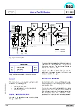
The injection pumps are installed on the roller guide
housings directly above the camshaft, and they are
activated by the cams on the camshaft through roller
guides fitted in the roller guide housings.
The amount of fuel injected into each cylinder unit is
adjusted by means of the governor, which maintains
the engine speed at the preset value by a continuous
positioning of the fuel pump racks, via a common
regulating shaft and spring-loaded linkages for each
pump.
The injection valve is for "deep" building-in to the
centre of the cylinder head.
The injection oil is supplied from the injection pump
to the injection valve via a double-walled pressure
pipe installed in a bore, in the cylinder head.
This bore has an external connection to conduct the
leak oil from the injection valve and high-pressure
pipe to the waste oil system.
A bore in the cylinder head vents the space below the
bottom rubber sealing ring on the injection valve,
thus preventing any pressure build-up due to gas
leakage, but also unveiling any malfunction of the
bottom rubber sealing ring for leak oil.
Waste Oil System
Waste and leak oil from the comparements, fuel
valves and engine feed pump is led to a fuel leakage
alarm unit.
L28/32H
Internal Fuel Oil System
1607543-9.5
Page 2 (2)
99.48
The alarm unit consists of a box with a float switch for
level monitoring. In case of a larger than normal
leakage, the float switch will initiate alarm. The
supply fuel oil to the engine is lead through the unit
in order to keep this heated up, thereby ensuring free
drainage passage even for high-viscous waste/leak
oil.
Optionals
Besides the standard components, the following
standard optionals can be built-on:
–
Engine driven fuel oil pump
Pressure differential alarm high
–
PDAH 43-40 Fuel oil, inlet and outlet filter
Pressure differential transmitting
–
PDT 43-40 Fuel oil, inlet and outlet filter
Pressure alarm low
–
PAL 40 Fuel oil, inlet fuel oil pump
Pressure transmitting
–
PT40 Fuel oil, inlet fuel oil pump
Temperature element
–
TE40 Fuel oil, inlet fuel oil pump
Data
For pump capacities, see D 10 05 0 "List of Capa-
cities".
Set points and operating levels for temperature and
pressure are stated in B 19 00 0 "Operating Data and
Set Points".
Summary of Contents for L28/32H
Page 4: ......
Page 5: ...Introduction I 00...
Page 6: ......
Page 8: ......
Page 10: ......
Page 11: ...Designation of Cylinders In Line 98 19 1607568 0 1 Page 1 1 I 00 15 0...
Page 12: ......
Page 18: ......
Page 19: ...General information D 10...
Page 20: ......
Page 22: ......
Page 24: ......
Page 26: ......
Page 30: ......
Page 32: ......
Page 34: ......
Page 36: ......
Page 37: ...Basic Diesel Engine B 10...
Page 38: ......
Page 44: ......
Page 45: ...99 40 B 10 01 1 L28 32H Cross Section 1607528 5 2 Page 1 1...
Page 46: ......
Page 48: ......
Page 50: ......
Page 52: ......
Page 54: ......
Page 58: ......
Page 59: ...1607566 7 1 Page 1 1 Engine Rotation Clockwise B 10 11 1 General 98 18...
Page 60: ......
Page 61: ...Fuel Oil System B 11...
Page 62: ......
Page 68: ......
Page 72: ......
Page 74: ......
Page 76: ......
Page 79: ...Lubrication Oil System B 12...
Page 80: ......
Page 86: ......
Page 88: ......
Page 91: ...Cooling Water System B 13...
Page 92: ......
Page 98: ......
Page 106: ......
Page 108: ......
Page 112: ......
Page 113: ...Compressed Air System B 14...
Page 114: ......
Page 118: ......
Page 119: ...Combustion Air System B 15...
Page 120: ......
Page 124: ......
Page 126: ...Fig 1 Jet system 1639456 5 0 Page 2 2 Lambda Controller 93 44 L28 32H B 15 11 1...
Page 127: ...Exhaust Gas System B 16...
Page 128: ......
Page 136: ......
Page 140: ......
Page 142: ......
Page 144: ......
Page 146: ......
Page 147: ...Speed Control System B 17...
Page 148: ......
Page 150: ......
Page 152: ......
Page 153: ...Monitoring Equipment B 18...
Page 154: ......
Page 156: ......
Page 158: ......
Page 159: ...Safety and Control System B 19...
Page 160: ......
Page 164: ......
Page 166: ......
Page 177: ...Foundation B 20...
Page 178: ......
Page 180: ......
Page 183: ...Test running B 21...
Page 184: ......
Page 186: ......
Page 187: ...Spare Parts E 23...
Page 188: ......
Page 190: ......
Page 191: ...99 35 1607521 2 6 Page 1 1 Recommended Wearing Parts E 23 04 0 L28 32H...
Page 192: ......
Page 195: ...Tools P 24...
Page 196: ......
Page 200: ......
Page 202: ......
Page 203: ...Preservation and Packing B 25...
Page 204: ......
Page 206: ......
Page 208: ......
Page 210: ......
Page 211: ...Alternator G 50...
Page 212: ......
Page 216: ......
Page 218: ......

