08028-0D\H5250\94.08.12
91.39
1624464-1.0
Page 2 (2)
System Design
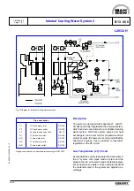
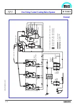
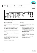
The system is a central cooling water system of
simple design with only one central cooler. Low
temperature (LT) and fresh water (FW) pumps are
common for all engines. In order to minimize the
power consumption the LT FW pump installation
consists of 3 pumps, two for sea operation and
smaller one for harbour operation.
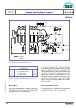
The GenSet engines are connected as a one string
plant, with only one inlet- and outlet cooling water
connection and with internal HT-circuit, see also B
13 00 0 “Internal cooling water system 1”, describing
this system.
The propulsion engines HT-circuit is built up acc. to
the same principle, i.e. HT-water temperature is
adjusted with LT-water mixing by means of the
thermostatic valve.
The system is also remarkable for its preheating of
stand-by GenSet engines and propulsion engine by
running GenSets, without extra pumps and heaters.
Preheating of Stand-by GenSets during Sea-
operation:
GenSets in stand-by position are preheated
automatically via the venting pipe with water from the
running engines. This is possible due to the pressure
difference, which the running GenSet engines HT-
pumps produce.
Preheating of Stand-by GenSets and Propulsion
Engine during Harbour Operation:
During harbour stay the propulsion and GenSet
engines are also preheated in stand-by position by
the running GenSets. Valve (1) is open and valve (2)
is closed. Thus the propulsion engine is heated from
top and downwards, which is the most economic
solution.
B 13 00 0
General
One String Central Cooling Water System
Summary of Contents for L28/32H
Page 4: ......
Page 5: ...Introduction I 00...
Page 6: ......
Page 8: ......
Page 10: ......
Page 11: ...Designation of Cylinders In Line 98 19 1607568 0 1 Page 1 1 I 00 15 0...
Page 12: ......
Page 18: ......
Page 19: ...General information D 10...
Page 20: ......
Page 22: ......
Page 24: ......
Page 26: ......
Page 30: ......
Page 32: ......
Page 34: ......
Page 36: ......
Page 37: ...Basic Diesel Engine B 10...
Page 38: ......
Page 44: ......
Page 45: ...99 40 B 10 01 1 L28 32H Cross Section 1607528 5 2 Page 1 1...
Page 46: ......
Page 48: ......
Page 50: ......
Page 52: ......
Page 54: ......
Page 58: ......
Page 59: ...1607566 7 1 Page 1 1 Engine Rotation Clockwise B 10 11 1 General 98 18...
Page 60: ......
Page 61: ...Fuel Oil System B 11...
Page 62: ......
Page 68: ......
Page 72: ......
Page 74: ......
Page 76: ......
Page 79: ...Lubrication Oil System B 12...
Page 80: ......
Page 86: ......
Page 88: ......
Page 91: ...Cooling Water System B 13...
Page 92: ......
Page 98: ......
Page 106: ......
Page 108: ......
Page 112: ......
Page 113: ...Compressed Air System B 14...
Page 114: ......
Page 118: ......
Page 119: ...Combustion Air System B 15...
Page 120: ......
Page 124: ......
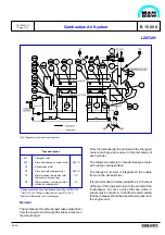
Page 126: ...Fig 1 Jet system 1639456 5 0 Page 2 2 Lambda Controller 93 44 L28 32H B 15 11 1...
Page 127: ...Exhaust Gas System B 16...
Page 128: ......
Page 136: ......
Page 140: ......
Page 142: ......
Page 144: ......
Page 146: ......
Page 147: ...Speed Control System B 17...
Page 148: ......
Page 150: ......
Page 152: ......
Page 153: ...Monitoring Equipment B 18...
Page 154: ......
Page 156: ......
Page 158: ......
Page 159: ...Safety and Control System B 19...
Page 160: ......
Page 164: ......
Page 166: ......
Page 177: ...Foundation B 20...
Page 178: ......
Page 180: ......
Page 183: ...Test running B 21...
Page 184: ......
Page 186: ......
Page 187: ...Spare Parts E 23...
Page 188: ......
Page 190: ......
Page 191: ...99 35 1607521 2 6 Page 1 1 Recommended Wearing Parts E 23 04 0 L28 32H...
Page 192: ......
Page 195: ...Tools P 24...
Page 196: ......
Page 200: ......
Page 202: ......
Page 203: ...Preservation and Packing B 25...
Page 204: ......
Page 206: ......
Page 208: ......
Page 210: ......
Page 211: ...Alternator G 50...
Page 212: ......
Page 216: ......
Page 218: ......

