08028-0D\H5250\94.08.12
94.17
General
Governor Type
As standard, the engines are equipped with a
mechanical - hydraulic Woodward governor type
UG8D.
Speed Adjustment
Electrical remote adjustment or manual adjustment
on the governor.
Speed Adjustment Range
Between -5% and +10% of the nominal speed at idle
running.
Droop
Droop adjustable between 0% and 7% of the nominel
speed; normally adjusted at 3.5% speed rise when
load is taken off from full load to idle running.
1639468-5.0
Page 1 (1)
Governor
B 17 01 1
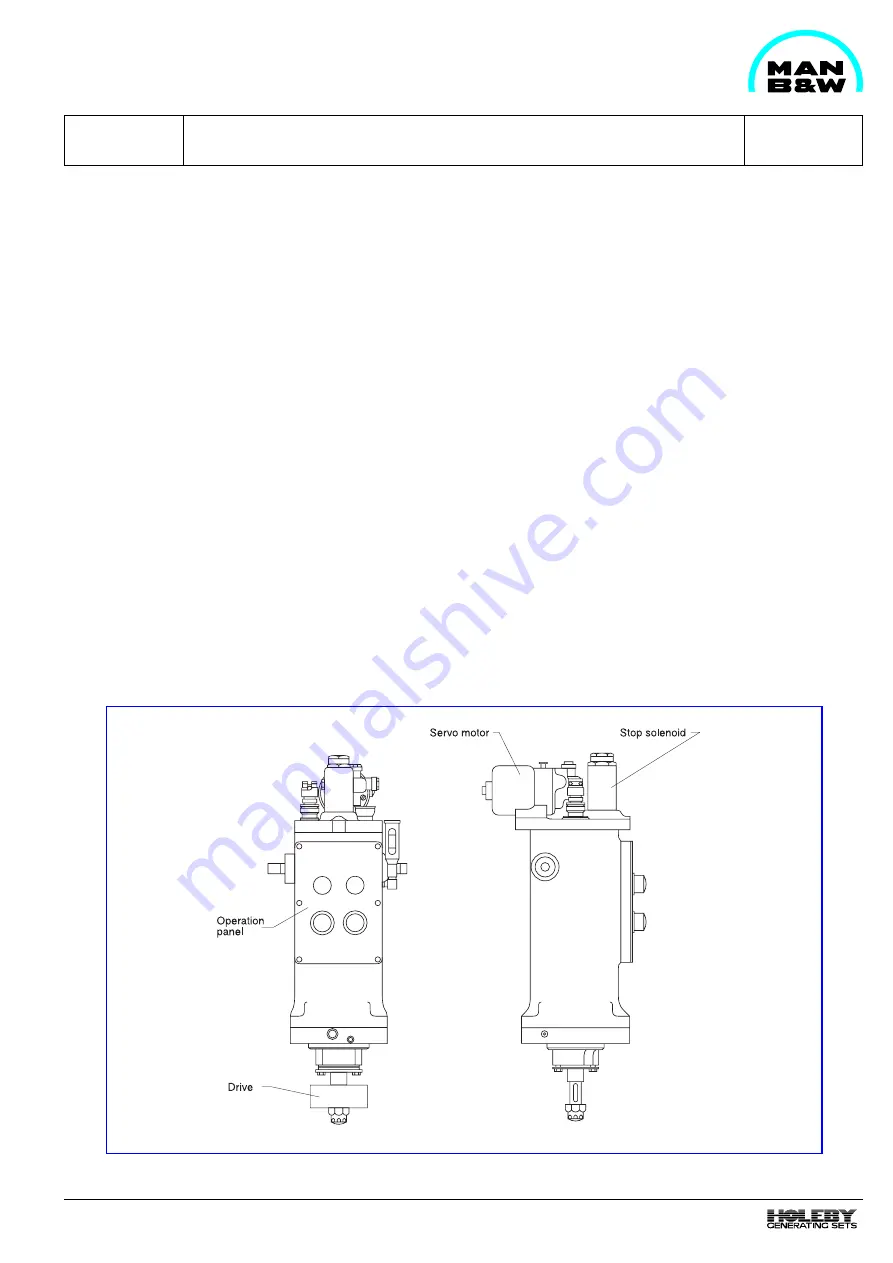
Fig 1 Woodward governor
0% droop is only possible for single engines in solo
operation. In the case of solo and mains parallel
operation, 3 to 5% droop is required.
In the case of electronic speed control, 0% droop is
possible for parallel operation as well.
Load Distribution
By the droop.
Shut-down/Stop
By shut-down or stop the stop solenoid is energized
24 V DC.
Summary of Contents for L28/32H
Page 4: ......
Page 5: ...Introduction I 00...
Page 6: ......
Page 8: ......
Page 10: ......
Page 11: ...Designation of Cylinders In Line 98 19 1607568 0 1 Page 1 1 I 00 15 0...
Page 12: ......
Page 18: ......
Page 19: ...General information D 10...
Page 20: ......
Page 22: ......
Page 24: ......
Page 26: ......
Page 30: ......
Page 32: ......
Page 34: ......
Page 36: ......
Page 37: ...Basic Diesel Engine B 10...
Page 38: ......
Page 44: ......
Page 45: ...99 40 B 10 01 1 L28 32H Cross Section 1607528 5 2 Page 1 1...
Page 46: ......
Page 48: ......
Page 50: ......
Page 52: ......
Page 54: ......
Page 58: ......
Page 59: ...1607566 7 1 Page 1 1 Engine Rotation Clockwise B 10 11 1 General 98 18...
Page 60: ......
Page 61: ...Fuel Oil System B 11...
Page 62: ......
Page 68: ......
Page 72: ......
Page 74: ......
Page 76: ......
Page 79: ...Lubrication Oil System B 12...
Page 80: ......
Page 86: ......
Page 88: ......
Page 91: ...Cooling Water System B 13...
Page 92: ......
Page 98: ......
Page 106: ......
Page 108: ......
Page 112: ......
Page 113: ...Compressed Air System B 14...
Page 114: ......
Page 118: ......
Page 119: ...Combustion Air System B 15...
Page 120: ......
Page 124: ......
Page 126: ...Fig 1 Jet system 1639456 5 0 Page 2 2 Lambda Controller 93 44 L28 32H B 15 11 1...
Page 127: ...Exhaust Gas System B 16...
Page 128: ......
Page 136: ......
Page 140: ......
Page 142: ......
Page 144: ......
Page 146: ......
Page 147: ...Speed Control System B 17...
Page 148: ......
Page 150: ......
Page 152: ......
Page 153: ...Monitoring Equipment B 18...
Page 154: ......
Page 156: ......
Page 158: ......
Page 159: ...Safety and Control System B 19...
Page 160: ......
Page 164: ......
Page 166: ......
Page 177: ...Foundation B 20...
Page 178: ......
Page 180: ......
Page 183: ...Test running B 21...
Page 184: ......
Page 186: ......
Page 187: ...Spare Parts E 23...
Page 188: ......
Page 190: ......
Page 191: ...99 35 1607521 2 6 Page 1 1 Recommended Wearing Parts E 23 04 0 L28 32H...
Page 192: ......
Page 195: ...Tools P 24...
Page 196: ......
Page 200: ......
Page 202: ......
Page 203: ...Preservation and Packing B 25...
Page 204: ......
Page 206: ......
Page 208: ......
Page 210: ......
Page 211: ...Alternator G 50...
Page 212: ......
Page 216: ......
Page 218: ......

