08028-0D\H5250\94.08.12
1631472-4.1
Page 1 (3)
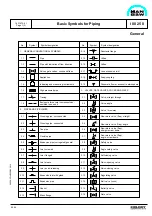
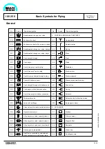
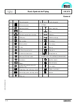
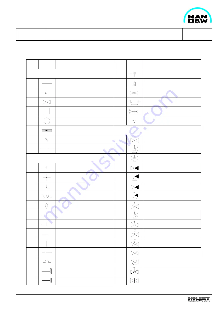
Basic Symbols for Piping
I 00 25 0
General
93.44
1.1
1.2
1.3
1.4
1.5
1.6
1.7
1.8
No.
Symbol
Symbol designation
1.
GENERAL CONVENTIONAL SYMBOLS
2.
PIPES AND PIPE JOINTS
2.1
2.2
2.3
2.4
2.5
2.6
2.7
2.8
2.9
2.10
2.11
2.12
2.13
2.14
2.15
2.16
2.17
2.18.
2.19
No.
Symbol
Symbol designation
3.
VALVES, GATE VALVES, COCKS AND FLAPS
3.1
3.2
3.3
3.4
3.5
3.6
3.7
3.8
3.9
3.10
3.11
3.12
3.13
3.14
3.15
3.16
Pipe
Pipe with indication of flow direction
Valves, gate valves, cocks and flaps
Appliances
Indicating and measuring instruments
High pressured pipe
Tracing
Crossing pipe, not connected
Crossing pipe, connected
Tee pipe
Flexible pipe
Expansion pipe (corrugated) general
Joint, screwed
Joint, flanged
Joint, sleeve
Joint, quick-releasing
Expansion joint with gland
Expansion pipe
Cap nut
Blank flange
Spectacle flange
Orifice
Orifice
Loop expansion joint
Snap-coupling
Pneumatic flow or exhaust to atmosphere
Valve, straight through
Valve, angle
Valve, three-way
Non-return valve (flap), straight
Non-return valve (flap), angle
Non-return valve (flap),
straight screw down
Non-return valve (flap),
angle, screw down
Safety valve
Angle safety valve
Self-closing valve
Quick-opening valve
Quick-closing valve
Regulating valve
Ball valve (-cock)
Butterfly valve
Gate valve
Enclosure for several components as-
sembled in one unit
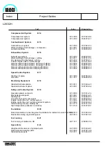
Summary of Contents for L28/32H
Page 4: ......
Page 5: ...Introduction I 00...
Page 6: ......
Page 8: ......
Page 10: ......
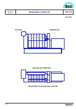
Page 11: ...Designation of Cylinders In Line 98 19 1607568 0 1 Page 1 1 I 00 15 0...
Page 12: ......
Page 18: ......
Page 19: ...General information D 10...
Page 20: ......
Page 22: ......
Page 24: ......
Page 26: ......
Page 30: ......
Page 32: ......
Page 34: ......
Page 36: ......
Page 37: ...Basic Diesel Engine B 10...
Page 38: ......
Page 44: ......
Page 45: ...99 40 B 10 01 1 L28 32H Cross Section 1607528 5 2 Page 1 1...
Page 46: ......
Page 48: ......
Page 50: ......
Page 52: ......
Page 54: ......
Page 58: ......
Page 59: ...1607566 7 1 Page 1 1 Engine Rotation Clockwise B 10 11 1 General 98 18...
Page 60: ......
Page 61: ...Fuel Oil System B 11...
Page 62: ......
Page 68: ......
Page 72: ......
Page 74: ......
Page 76: ......
Page 79: ...Lubrication Oil System B 12...
Page 80: ......
Page 86: ......
Page 88: ......
Page 91: ...Cooling Water System B 13...
Page 92: ......
Page 98: ......
Page 106: ......
Page 108: ......
Page 112: ......
Page 113: ...Compressed Air System B 14...
Page 114: ......
Page 118: ......
Page 119: ...Combustion Air System B 15...
Page 120: ......
Page 124: ......
Page 126: ...Fig 1 Jet system 1639456 5 0 Page 2 2 Lambda Controller 93 44 L28 32H B 15 11 1...
Page 127: ...Exhaust Gas System B 16...
Page 128: ......
Page 136: ......
Page 140: ......
Page 142: ......
Page 144: ......
Page 146: ......
Page 147: ...Speed Control System B 17...
Page 148: ......
Page 150: ......
Page 152: ......
Page 153: ...Monitoring Equipment B 18...
Page 154: ......
Page 156: ......
Page 158: ......
Page 159: ...Safety and Control System B 19...
Page 160: ......
Page 164: ......
Page 166: ......
Page 177: ...Foundation B 20...
Page 178: ......
Page 180: ......
Page 183: ...Test running B 21...
Page 184: ......
Page 186: ......
Page 187: ...Spare Parts E 23...
Page 188: ......
Page 190: ......
Page 191: ...99 35 1607521 2 6 Page 1 1 Recommended Wearing Parts E 23 04 0 L28 32H...
Page 192: ......
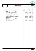
Page 195: ...Tools P 24...
Page 196: ......
Page 200: ......
Page 202: ......
Page 203: ...Preservation and Packing B 25...
Page 204: ......
Page 206: ......
Page 208: ......
Page 210: ......
Page 211: ...Alternator G 50...
Page 212: ......
Page 216: ......
Page 218: ......


