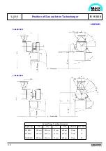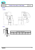
L28/32H
E 16 04 2
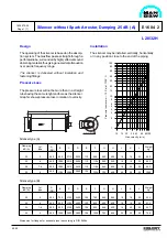
Silencer without Spark Arrestor, Damping 25 dB (A)
1609575-0.3
Page 1 (1)
99.40
Cyl.
type
Damping
dB (A)
Weight
kg
L
K
J
H
G
F
E
D
C
B
A
(DN)
750
800
900
1000
400
450
500
550
3100
3100
3300
3500
3400
3400
3600
3800
150
150
150
150
780
830
930
1030
540
595
645
703
495
550
600
650
16
16
16
20
16
16
20
20
22
22
22
22
432
473
597
798
25
25
25
25
Cyl.
type
Damping
dB (A)
Weight
kg
L
K
J
H
G
F
E
D
C
B
A
(DN)
938
1084
1084
1184
400
450
500
550
2710
3210
3210
3260
2930
3430
3430
3500
110
110
110
120
958
1104
1104
1204
540
595
645
703
495
550
600
650
16
16
16
20
16
16
20
20
22
22
22
22
600
820
850
1050
25
25
25
25
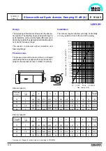
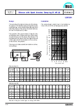
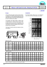
Silencer type (A)
Silencer type (B)
Dimension for flanges for exhaust pipes is according to DIN 86044
K number of holes
øL
H
G
A
B
F
J
E
E
C
D
5
6
7-8
9
5
6
7-8
9
Installation
The silencer may be installed, vertically, horizontally
or in any position close to the end of the piping.
Design
The operating of the silencer is based on the absorp-
tion system. The Gasflow passes straight-through a
perforated tube, surrounded by highly effecient sound
absorbing material, thus giving an excellent attenuation
over a wide frequency range.
The silencer is delivered without insulation and
fastening fittings.
Pressure Loss
The pressure loss will not be more then in a straight
tube having the same lenght and bore as the silencer.
Graphic shows pressure loss in relation to velocity.
10
15 20
30 40
60 80100
Gas velocity (m/s)
60
80
30
20
15
10
8
6
5
4
3
2
1
40
100
Pressure loss (mm w ~ 10 Pa) at T300° C.
Summary of Contents for L28/32H
Page 4: ......
Page 5: ...Introduction I 00...
Page 6: ......
Page 8: ......
Page 10: ......
Page 11: ...Designation of Cylinders In Line 98 19 1607568 0 1 Page 1 1 I 00 15 0...
Page 12: ......
Page 18: ......
Page 19: ...General information D 10...
Page 20: ......
Page 22: ......
Page 24: ......
Page 26: ......
Page 30: ......
Page 32: ......
Page 34: ......
Page 36: ......
Page 37: ...Basic Diesel Engine B 10...
Page 38: ......
Page 44: ......
Page 45: ...99 40 B 10 01 1 L28 32H Cross Section 1607528 5 2 Page 1 1...
Page 46: ......
Page 48: ......
Page 50: ......
Page 52: ......
Page 54: ......
Page 58: ......
Page 59: ...1607566 7 1 Page 1 1 Engine Rotation Clockwise B 10 11 1 General 98 18...
Page 60: ......
Page 61: ...Fuel Oil System B 11...
Page 62: ......
Page 68: ......
Page 72: ......
Page 74: ......
Page 76: ......
Page 79: ...Lubrication Oil System B 12...
Page 80: ......
Page 86: ......
Page 88: ......
Page 91: ...Cooling Water System B 13...
Page 92: ......
Page 98: ......
Page 106: ......
Page 108: ......
Page 112: ......
Page 113: ...Compressed Air System B 14...
Page 114: ......
Page 118: ......
Page 119: ...Combustion Air System B 15...
Page 120: ......
Page 124: ......
Page 126: ...Fig 1 Jet system 1639456 5 0 Page 2 2 Lambda Controller 93 44 L28 32H B 15 11 1...
Page 127: ...Exhaust Gas System B 16...
Page 128: ......
Page 136: ......
Page 140: ......
Page 142: ......
Page 144: ......
Page 146: ......
Page 147: ...Speed Control System B 17...
Page 148: ......
Page 150: ......
Page 152: ......
Page 153: ...Monitoring Equipment B 18...
Page 154: ......
Page 156: ......
Page 158: ......
Page 159: ...Safety and Control System B 19...
Page 160: ......
Page 164: ......
Page 166: ......
Page 177: ...Foundation B 20...
Page 178: ......
Page 180: ......
Page 183: ...Test running B 21...
Page 184: ......
Page 186: ......
Page 187: ...Spare Parts E 23...
Page 188: ......
Page 190: ......
Page 191: ...99 35 1607521 2 6 Page 1 1 Recommended Wearing Parts E 23 04 0 L28 32H...
Page 192: ......
Page 195: ...Tools P 24...
Page 196: ......
Page 200: ......
Page 202: ......
Page 203: ...Preservation and Packing B 25...
Page 204: ......
Page 206: ......
Page 208: ......
Page 210: ......
Page 211: ...Alternator G 50...
Page 212: ......
Page 216: ......
Page 218: ......

