08028-0D/H5250/94.08.12
1607535-6.6
Page 1 (1)
List of Capacities
D 10 05 0
L28/32H
99.33
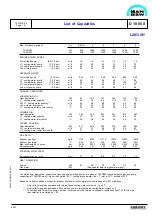
Max. continuous rating at Cyl. 5-ECR 5 6 7 8 9
720 RPM kW 875 1050 1260 1470 1680 1890
750 RPM kW 925 1100 1320 1540 1760 1980
ENGINE-DRIVEN PUMPS.
Fuel oil feed pump (5.5-7.5 bar) m
3
/h 1.4 1.4 1.4 1.4 1.4 1.4
L.T. cooling water pump (1-2.5 bar) m
3
/h 45 45 60 75 75 75
H.T. cooling water pump (1-2.5 bar) m
3
/h 45 45 45 60 60 60
Lub. oil main pump (3-5 bar) m
3
/h 24 24 24 33 33 33
SEPARATE PUMPS:
Fuel oil feed pump *** (4-10 bar) m
3
/h 0.25 0.31 0.36 0.43 0.49 0.55
L.T. cooling water pump* (1-2.5 bar) m
3
/h 45 45 54 65 77 89
L.T. cooling water pump** (1-2.5 bar) m
3
/h 65 65 73 95 105 115
H.T. cooling water pump (1-2.5 bar) m
3
/h 37 37 45 50 55 60
Lub. oil stand-by pump (3-5 bar) m
3
/h 22 22 23 25 27 28
COOLING CAPACITIES:
LUBRICATING OIL:
Heat dissipation kW 91 105 127 149 172 194
L.T. cooling water quantity* m
3
/h 6.4 7.8 9.4 11.0 12.7 14.4
SW L.T. cooling water quantity** m
3
/h 28 28 28 40 40 40
Lub. oil temp. inlet cooler °C 67 67 67 67 67 67
L.T. cooling water temp. inlet cooler °C 36 36 36 36 36 36
CHARGE AIR:
Heat dissipation kW 305 393 467 541 614 687
L.T. cooling water quantity m
3
/h 37 37 45 55 65 75
L.T. cooling water inlet cooler °C 36 36 36 36 36 36
JACKET COOLING:
Heat dissipation kW 211 264 320 375 432 489
H.T. cooling water quantity m
3
/h 37 37 45 50 55 60
H.T. cooling water temp. inlet cooler °C 77 77 77 77 77 77
GAS DATA:
Exhaust gas flow kg/h 7710 9260 11110 12970 14820 16670
Exhaust gas temp. °C 305 305 305 305 305 305
Max. allowable back. press. bar 0.025 0.025 0.025 0.025 0.025 0.025
Air consumption kg/s 2.09 2.51 3.02 3.52 4.02 4.53
STARTING AIR SYSTEM:
Air consumption per start Nm
3
0.7 0.7 0.8 0.9 1.0 1.1
HEAT RADIATION:
Engine kW 22 26 32 38 44 50
Generator kW (See separat data from generator maker)
The stated heat dissipation, capacities of gas and engine-driven pumps are given at 720 RPM. Heat dissipation gas and pump
capaci-ties at 750 RPM are 4% higher than stated. If L.T. cooling are sea water, the L.T. inlet is 32° C instead of 36°C.
Based on tropical conditions, except for exhaust flow and air consumption which are based on ISO conditions.
* Only valid for engines equipped with internal basic cooling water system no. 1 and 2.
** Only valid for engines equipped with combined coolers, internal basic cooling water system no. 3.
*** To compensate for built on pumps, ambient condition, calorific value and adequate circulations flow. The ISO fuel oil
consumption is multiplied by 1.45.
Summary of Contents for L28/32H
Page 4: ......
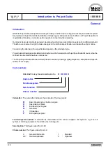
Page 5: ...Introduction I 00...
Page 6: ......
Page 8: ......
Page 10: ......
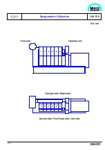
Page 11: ...Designation of Cylinders In Line 98 19 1607568 0 1 Page 1 1 I 00 15 0...
Page 12: ......
Page 18: ......
Page 19: ...General information D 10...
Page 20: ......
Page 22: ......
Page 24: ......
Page 26: ......
Page 30: ......
Page 32: ......
Page 34: ......
Page 36: ......
Page 37: ...Basic Diesel Engine B 10...
Page 38: ......
Page 44: ......
Page 45: ...99 40 B 10 01 1 L28 32H Cross Section 1607528 5 2 Page 1 1...
Page 46: ......
Page 48: ......
Page 50: ......
Page 52: ......
Page 54: ......
Page 58: ......
Page 59: ...1607566 7 1 Page 1 1 Engine Rotation Clockwise B 10 11 1 General 98 18...
Page 60: ......
Page 61: ...Fuel Oil System B 11...
Page 62: ......
Page 68: ......
Page 72: ......
Page 74: ......
Page 76: ......
Page 79: ...Lubrication Oil System B 12...
Page 80: ......
Page 86: ......
Page 88: ......
Page 91: ...Cooling Water System B 13...
Page 92: ......
Page 98: ......
Page 106: ......
Page 108: ......
Page 112: ......
Page 113: ...Compressed Air System B 14...
Page 114: ......
Page 118: ......
Page 119: ...Combustion Air System B 15...
Page 120: ......
Page 124: ......
Page 126: ...Fig 1 Jet system 1639456 5 0 Page 2 2 Lambda Controller 93 44 L28 32H B 15 11 1...
Page 127: ...Exhaust Gas System B 16...
Page 128: ......
Page 136: ......
Page 140: ......
Page 142: ......
Page 144: ......
Page 146: ......
Page 147: ...Speed Control System B 17...
Page 148: ......
Page 150: ......
Page 152: ......
Page 153: ...Monitoring Equipment B 18...
Page 154: ......
Page 156: ......
Page 158: ......
Page 159: ...Safety and Control System B 19...
Page 160: ......
Page 164: ......
Page 166: ......
Page 177: ...Foundation B 20...
Page 178: ......
Page 180: ......
Page 183: ...Test running B 21...
Page 184: ......
Page 186: ......
Page 187: ...Spare Parts E 23...
Page 188: ......
Page 190: ......
Page 191: ...99 35 1607521 2 6 Page 1 1 Recommended Wearing Parts E 23 04 0 L28 32H...
Page 192: ......
Page 195: ...Tools P 24...
Page 196: ......
Page 200: ......
Page 202: ......
Page 203: ...Preservation and Packing B 25...
Page 204: ......
Page 206: ......
Page 208: ......
Page 210: ......
Page 211: ...Alternator G 50...
Page 212: ......
Page 216: ......
Page 218: ......

