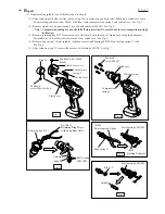
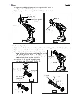

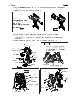

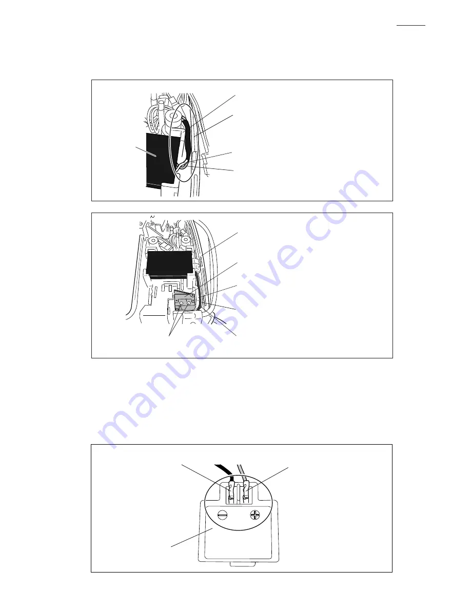
(5) Wiring near the terminal
1. Connect Terminal to Motor control unit as follows.
There is a flag receptacle on each of the two lead wires (black one and red one) from Motor
control unit.
Connect these receptacles with Terminal as illustrated in Fig. F.
Be sure to connect the flag receptacle on the red lead wire to the (+) terminal, and connect
the other one on the black lead wire to the (-) terminal.
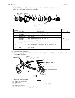
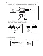
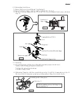
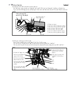
(4) Wiring near the buzzer circuit and interlock switch
Place the lead wires from Buzzer between the boss and the wall of Housing R as illustrated in Fig. D.
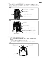
And then fix Interlock switch unit to Housing R by fitting the through holes of the Switch unit to the bosses
on Housing R as illustrated in Fig. E.
Lead wire from Buzzer (white)
Boss of Housing R for holding Buzzer
Wall of Housing R
Lead wire from Buzzer (red)
Buzzer
Fig. D
Fig. E
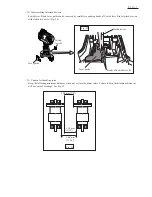
Fig. F
Interlock switch unit
Boss for protecting Interlock switch unit
Bosses on Housing R
Housing R
Lead wire from Interlock switch unit (red)
Lead wire from Interlock switch unit (yellow)
Flag receptacle on
black lead wire
Flag receptacle
on red lead wire
Terminal
P 15 / 17