


R
epair
P 10 / 17
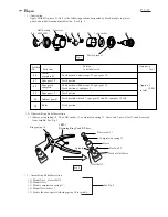
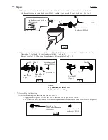
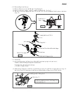
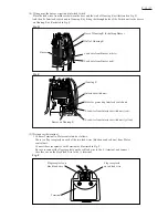
( 9) Insert armature into motor control unit. See Fig. 47. The assembling of motor section has been completed
in this step.
(10) Join the motor section to the gear section. See Fig. 48.
Fig. 49
Fig. 50
<Note>
Be careful, not to be pinched
your finger between motor control
unit and rotor.
Because, rotor is pulled toward
motor control unit by the strong
magnetic force.
Motor control unit
Rotor
Fig. 47
Fig. 48
Gear section
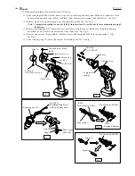
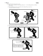
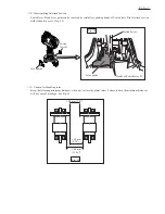
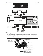
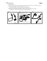
(11) Facing switch unit to the plate installing side, mount the motor and gear section to housing R.
and mount trigger switch section, LED circuit to housing R. See Fig. 49.
(12) Mount plate and lens. And secure housing L with 8 pcs. of pan head screw M3x20. See Fig. 50.
Pan head
screws M3x20
Housing L
Housing R
Plate
Lens
Switch unit
Plate installing side
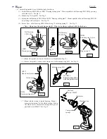
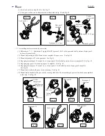
Spacer
Terminal
Lever guide
Trigger switch
section
Buzzer
circuit
(for BFH...F series)
LED circuit
(for BFH...F series)
Switch
lever B
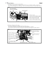
As for buzzer circuit, lever guide, switch lever B and interlock switch, mount as illustrated in Fig. 49A
and Fig. 49B.
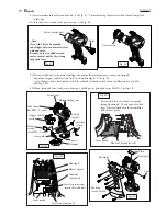
Interlock
switch
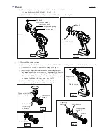
Hooks of Switch lever B
Lever guide
Fig. 49A
Press switch lever B toward lever guide
through housing R. Then hooks of switch
lever B are interlocked in the assembling
hole of lever guide.
Interlock
switch unit
Buzzer circuit
Boss for protecting
interlock switch unit
Bosses on Housing R
Housing R
Lever guide
Fig. 49B


