
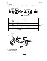

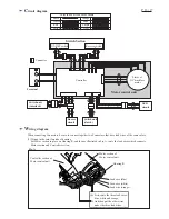


C
ircuit diagram
P 13 / 17
ON/OFF switch
Switch Section
Motor control unit
Terminal
Stator of
DC brushless
motor
Color index of lead wires' sheath
Black
White
Red
Orange
Blue
Yellow
Purple
Gray
Buzzer
circuit
Switch unit
(clutch)
Switch unit
(interlock)
LED
circuit
Reverse switch
Controller
Connector
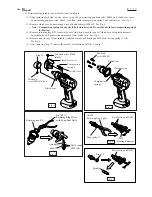
W
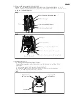
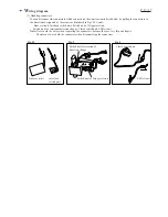
iring diagram
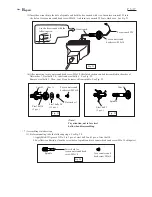
When connecting Connectors, be sure to connect together two Connectors that have lead wires of the same colors.
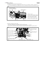
(1) Wiring in the rotor fan side of housing
Set Motor section in place on Housing R, and then as illustrated in Fig. A, route the lead wires which connects
Motor section and Controller section.
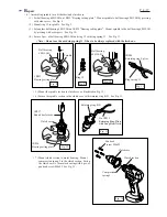
Housing R
Lead wire (blue)
Lead wire (white)
Lead wire (orange)
(1) First, route the three lead wires:
blue, white and orange.
(2) And then put the other wires
under the three lead wires.
Motor section of
Motor control unit
Controller section of
Motor control unit
Fig. A