


P 11 / 17
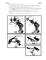
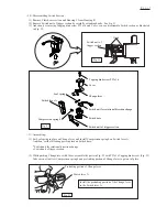
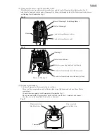
(1) Remove Clutch case section and Housing L from Housing R.
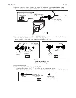
(2) Remove Switch unit of trigger section by carefully extending hooks. See Fig. 51
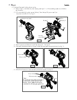
(3) And then, by removing Tapping bind screw PT3x16 and Cover, you can disassemble Switch section as illustrated
in Fig. 52;
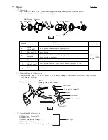
<10> Disassembling Switch Section
Hook
Switch unit of
trigger section
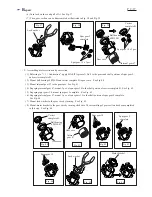
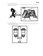
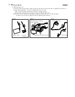
(1) Set Leaf spring in place on Change lever, and install Compression spring 4 on Switch lever A.
And then, set the following parts in place on Switch base;
Compression spring 4
Switch lever A
Change lever
Leaf spring
Switch unit for rotational direction change
Switch base
Switch unit of trigger section
Tapping bind screw PT3x16
Cover
Switch unit for rotational direction change
Switch unit of trigger section
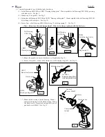
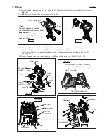
(2) While pushing Change lever with Cover, assemble the parts in Fig. 52 with PT3x16 Tapping bind screw. (Fig. 53)
Take care not to allow Compression spring 4 and protruding portion of Change lever to get out of place.
Protruding portion of Change lever
Install the protruding portion of the Change lever
in the Switch lever A.
Switch lever A
Fig. 51
Fig. 52
Fig. 53
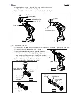
<11> Assembling: