


R
epair
P 5 / 17
Fig. 15
Fig. 16
Fig. 17
Fig. 18
Fig. 19
Fig. 20
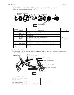
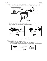
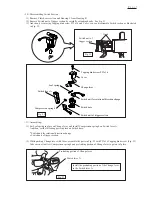
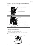
( 8 ) Mount compression spring 2 and switch lever. And secure clutch case cover
with pan head screw M4x8 (black). See Fig. 15.
( 9 ) Secure ring 38 to clutch case with pan head screw M4x4 (silver). See Fig. 16.
Pan head
screw M4x8 (black)
Clutch case cover
Clutch case
Compression spring 2
Switch lever
Pan head
screw M4x4 (silver)
Ring 38
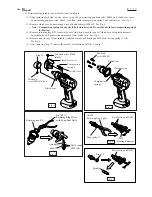
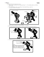
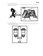
< 6 > Disassembling clutch section
( 1 ) Remove ring 38 and clutch case cover referring to "< 4 > Disassembling spindle (as a bit holder) and clutch case".
( 2 ) Remove clutch section from motor housing. See Fig. 17.
Clutch section
Compression
spring 5
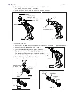
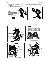
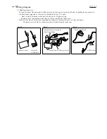
( 4 ) Remove adjust ring complete, flat washer 18 and
compression spring 19 from spindle. See Fig.20.
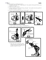
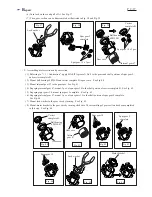
( 3 ) Insert torque adjust tool into the hole of adjust ring complete.
Turn torque adjust tool anti-clockwise, until adjust ring complete
is free from the compression spring 19. See Fig. 18.
Then, lock nut M12 can be separated from adjust ring complete
by turning clockwise with your hand. See Fig. 19.
Lock nut M12
Lock nut M12
Adjust ring
complete
Compression
spring 19
Torque adjust tool
(Standard equipment)
Adjust ring
complete
Compression
spring 19
Flat washer 18
Spindle