


R
epair
P 2 / 17
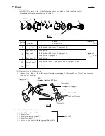
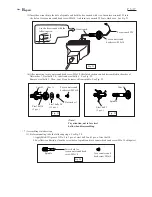
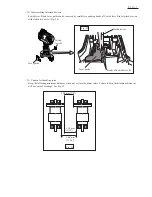
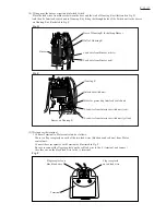
< 1 > Lubrication
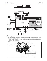
Apply MAKITA grease N. No.2 to the following portions designated by black triangle to protect
parts and product from unusual abrasion. See Fig. 1.
44
44
47
47
48
48
49
49
50
50
54
54
Position
No.
Parts item
Shaft portion which accept 47: spur gear 18.
Shaft portion which accept 49: spur gear 19.
Teeth portion of spur gear 9
Teeth portion
Teeth portion
Teeth portion where 47: spur gear 18 and 49: spur gear 19 roll.
Teeth portion
Spur gear 18
Spur gear 19
Rotor
Internal gear 47
Spur gear 9
complete
Carrier
complete B
Portion
to be lubricated
Amount : g
( oz )
Ball bearing
6805LLB
Gear case
Lock washer
Motor bracket
Approx. 2
(0.08)
in total
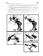
Fig. 2
Fig. 1
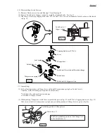
< 2 > Disassembling bit holder section
( 1 ) Remove ring spring 10. Then, flat washer 11, compression spring 13, sleeve and 2 pcs of steel 3 can be removed
from spindle. See Fig. 2.
1R291
Retaining Ring S and R Pliers
Spindle
Flat washer 11
Sleeve
Steel ball 3
Steel ball 3
Compression spring 13
Head of clutch case
Ring spring 10
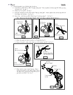
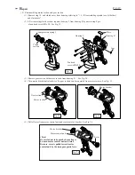
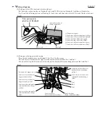
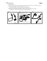
< 3 > Assembling bit holder section
( 1 ) Mount 2 pcs. of steel ball 3.
( 2 ) Mount sleeve.
( 3 ) Mount compression spring 13.
( 4 ) Mount flat washer 11.
( 5 ) Secure the above parts with ring spring 10 to spindle.
See Fig. 2.


