

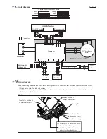

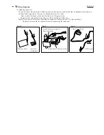

W
iring diagram
P 14 / 17
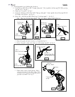
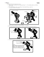
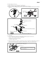
(3) Wiring near the trigger switch section
Place Switch section in place on Housing R. See Fig. C for the wiring.
The lead wires to Switch unit of Trigger section must be placed between Pin 1 and Pin 2.
Also do not fail to place the lead wire to Switch unit for rotational direction change between Pin 2 and Pin 3.
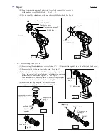
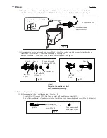
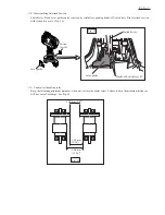
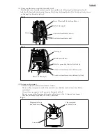
(2) Wiring near the LED circuit and clutch switch unit
Put Controller section in place on Housing R, and install LED circuit on Housing R. And then as illustrated in
Fig. B, pull the following parts out of Housing R: Lead wires and Connectors from LED circuit, Clutch switch unit.
1. Clutch switch unit
2. Lead wire to Motor control unit (yellow)
3. Lead wire to Motor control unit (purple)
4. Lead wire from LED circuit (gray)
5. Lead wire from LED circuit (blue)
6. Lead wire to Motor control unit (gray)
7. Lead wire to Motor control unit (blue)
These parts must be
placed out of Housing R.
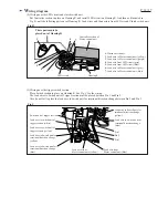
Fig. B
LED circuit
Fig. C
Controller section of
Motor control unit
Housing R
Pin1
Pin2
Pin3
Switch unit of trigger section
Lead wire to Switch unit for
rotational direction change
(yellow)
Lead wire to switch unit of
trigger section (white)
Lead wire to switch unit of
trigger section (yellow)
Lead wire to Switch unit for
rotational direction change
(blue)
Lead wire to Switch unit for
rotational direction change
(yellow)
Lead wire to Switch unit for
rotational direction change
(blue)
Lead wire from
Motor control unit (yellow)
Lead wire from
Motor control unit (blue)
1
2
3
4
5
6
7