background image


MAINTENANCE


87 

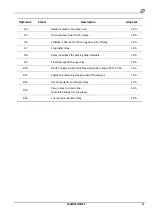
Reference 

Colour 

Description 

Amperes 

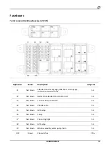
F11 

Brown 

Positive “15” right side low beams.


7.5 A 

F12 

Brown 

Positive “15” reversing lights and buzzer. 


7.5 A 

F13 

Brown 

Positive “15” parking brake control system.


5 A 

F14 

Brown 

Positive “15” slow/fast speed change.


7.5 A 

F15 

Brown 

Positive “15” available in motor plant line.


7.5 A 

F16 

Brown 

Positive “15” engine override.


7.5 A 

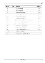
F17 


NOT CONNECTED 


F18 

Brown 

Positive “15” B90 Deutz urea temperature quality sensor.


7.5 A 

F19 

Red 

Positive “30” available in chassis plant line.


10 A 

F20 

Red 

Positive “15” air conditioner trinary pressure 

switch. 

10 A 

F21 

Red 

Positive “15” available in chassis plant line.


10 A 

F22 

Red 

Positive “30” available in chassis plant line.


10 A 

F23 

Red 

Positive “15” stop lights


10 A 

F24 

Blue 

Positive “15” setup.


15 A 

F25 

Yellow 

Positive “15” power supply 30 

R5. 

20 A 

F26 

Yellow 

Positive “15” electric fan

-2 oil radiator 

20 A 

F27 

Yellow 

Positive “15” electric fan

-1 oil radiator 

20 A 

F28 

Yellow 

Positive “15” B54 & B56 NOx sensors.


15 A 

F29 

Yellow 

Positive “15” Cabletronic chassis expansion control unit


20 A 

F30 

White 

Positive “15” Cabletronic chassis slave control unit


25 A 

F31 

Nut brown 

Positive “15” Deutz converter DC/DC power supply


5 A 

F32 

Green 

Positive “30” Deutz heated urea tubes


30 A 

F33 

Yellow 

Positive “30” Deutz engine fuel pump


20 A 

F34  

Yellow 

Positive “15” Danfoss engine fuel pump


20 A 

F35 

Pink 

Positive “15” left front stabilisers proximity switch


3 A 

Summary of Contents for RTH 4.18

Page 1: ...ION OF THE ORIGINAL INSTRUCTIONS Prepared in compliance with the essential requirement for the protection of health and safety 1 7 4 of annex I of directive 2006 42 EC Use and Maintenance Manual RTH Rotary telescopic elevators Deutz ...

Page 2: ...te Notes 0 04 2019 First release A 07 2019 Range of models updated B 12 2019 Range of models updated C 02 2020 Added specific Stage V 100kW drive unit D 11 2020 Added technical specifications automatic parking brake ...

Page 3: ...ices 19 Safety devices present 20 Residual risks 20 Hot fluid jets 20 Hot fluids and surfaces 20 Generic faults 21 Braking system accumulators 21 Reasonably foreseeable misuse 22 SECTION ON PRODUCT INFORMATION 23 TECHNICAL SPECIFICATIONS 24 DIMENSIONS 27 INFORMATION ON IDENTIFICATION 31 Vehicle s identification plate 31 Acoustic power emitted plate 31 Cab identification plate 31 Serial no stamped ...

Page 4: ...arking brake 62 Automatic parking brake 62 Driving the vehicle 65 OPERATING TECHNIQUES 66 Telescopic boom extension synchronisation 66 Installing the accessory 66 Dismantling the accessory 67 List of compatible accessories 68 Handling of loads 68 Picking up and placing a suspended load 70 Moving the centre of gravity 70 Visibility 71 Traversing over sloping ground 71 Climatic conditions of use 72 ...

Page 5: ...eck the slewing ring gear bearings for wear 108 Stabilisers 108 Wheels 108 Fuel tank 109 Window washing liquid tank 109 Hydraulic hoses 109 TROUBLESHOOTING 110 Error and display messages 110 Engine Troubleshooting 112 REFERENCE INFORMATION 123 Leaving the vehicle unused for long periods 123 Leaving the vehicle unused for less than 12 months 123 Reusing the vehicle 123 Dismantling and disposal of t...

Page 6: ......

Page 7: ...in safety standards and in compliance with the law Moreover it is necessary to ensure that the vehicle is not rendered hazardous by accidental damage or emergency maintenance carried out without authorisation Information regarding this Manual This Manual must be considered an integral part of the vehicle and must accompany it throughout its working life from commissioning to final disposal It must...

Page 8: ...arm system used to indicate the presence of an imminently dangerous situation which if not avoided can cause death or serious injury The symbols used in this Manual comply with standard UNI EN ISO 7010 2012 To make it easy for the user a summary of the symbols used is given below with their brief description Generic danger Danger of burns Danger of crushing Danger from hanging load Electrocution R...

Page 9: ...safety labels If a safety label is applied on a part of the vehicle that is to be replaced make sure the spare part has a similar label Contact your dealer for assistance in case of irreparably damaged labels missing labels and labels present on the vehicle but not described in this Manual Do not transport persons The safety symbol is applied near the mud guards engine compartment and the compartm...

Page 10: ...g Carefully read the Use and Maintenance Manual before starting the engine or carrying out maintenance or repairs Radiator This safety symbol is present on the upper part of the radiator inside the engine compartment Do not unscrew the radiator cap when the coolant is still hot The hot coolant is also pressurised and unscrewing the cap will cause ejection of boiling steam jets with risk of even se...

Page 11: ...Do not approach the accessory This safety symbol is applied at the top of the telescopic boom on the left side near the quick fit coupling for the accessories Do not approach the accessory fitted at the top of the boom during the working of the vehicle In particular do not climb on the accessory and do not stand in the area under it Speed limit on public roads These symbols applied on the sides an...

Page 12: ... are fitted correctly on the vehicle Keep the vehicle in perfect working condition by carrying out the scheduled maintenance punctually and scrupulously Unless otherwise specified carry out the maintenance operations with the vehicle in the maintenance position Dispose of the used liquids in compliance with the regulations in force in the country where the vehicle is used Clean the vehicle daily R...

Page 13: ... use compressed air for cleaning Avoid brushing materials containing asbestos Avoid grinding materials containing asbestos Use wet cleaning methods for parts containing asbestos Equip the work area with appropriate air extractors If there are no other methods for controlling the dusts wear a suitable respiratory mask Avoid areas where asbestos particles may be present in the air Prevention of cuts...

Page 14: ...te come in contact with the tissues Always wear protective goggles when acting on the batteries Wash hands thoroughly after touching the batteries or electric connectors Use of protective gloves is recommended Prevention of fires and explosions All fuels most lubricants and certain coolant mixtures are flammable Flammable fluids that come in contact with hot parts can cause fire leading to conside...

Page 15: ...ccordance with the regulatory standards in force Do not damage ether cylinders Keep ether cylinders out of reach of unauthorised persons Do not spray ether in an engine if the latter is fitted with thermal devices to facilitate start up in cold climates Piping Do not bend or damage the high pressure piping Do not install bent or damaged piping on the vehicle Repair or replace damaged piping prompt...

Page 16: ...Blue in accordance with the standards in force in the country in which the vehicle is used For drive units satisfying the Stage IV and Stage V anti pollution standards in order to protect the AdBlue purification system wait at least 5 minutes after the I C engine is switched off before acting on the main electric circuit to disconnect it Regeneration After a predefined period of use or use which a...

Page 17: ...rator in the cab must stay inside until the thunderstorm and lightning is over If on the ground during a thunderstorm with lightning the operator must move away from the vehicle and keep at a safe distance Spare parts and Equipment The Certificate of Conformity implies the Manufacturer s responsibility only for vehicles without modifications made by the user or by third parties and only equipped w...

Page 18: ...ke sure all the hoods are closed and all guards are installed correctly on the vehicle Always shut the cab door Lock the windows open or closed Clean all windows to ensure perfect visibility Adjust the seat so that the pedals can be pressed completely while sitting correctly Adjust the steering column inclination to ensure a comfortable posture and easy access to all the controls Check the conditi...

Page 19: ...e These operations will make the structure different from the original and cause invalidation of the certification Safety devices Before using the vehicle ensure that all safety devices are visible and working properly Should you find any anomalies in the safety devices stop working until the fault has been repaired Contact your dealer or Magni Telescopic Handlers After Sales Service Check that th...

Page 20: ...evices listed can be found in the relevant sections of this manual Residual risks DANGER OF CRUSHING Always stay at a safe distance from moving parts DANGER OF BURNS Pay the utmost attention to hot surfaces Hot fluid jets After operation the engine coolant is hot and under pressure Contact with hot water or steam leaks can cause severe burns Avoid possible injuries caused by hot water jets Do not ...

Page 21: ... RISK OF SLIPPING During operations carried out on site the areas around the equipment can contain various kinds of debris and liquids oil water etc that can make the ground slippery Be extremely careful RISK OF FALLING TRIPPING Be extremely careful when climbing up and down the vehicle CRUSHING OF LIMBS The presence of moving parts during operation can cause risks for ground operators When operat...

Page 22: ...to misuse the vehicle operating the vehicle on sloping ground without following the guidelines described in the relevant section of this manual the instinctive unforeseeable reaction of an operator in the event of a malfunction accident or breakdown while using the vehicle the operator using the vehicle with the feeling that the protection devices are only a hindrance to the operations to be carri...

Page 23: ...ON PRODUCT INFORMATION 23 SECTION ON PRODUCT INFORMATION Forklift truck with pivoting stabilisers RTH 4 18 RTH 5 18 RTH 5 21 RTH 5 23 RTH 5 25 Forklift truck with scissor stabilisers RTH 6 21 RTH 6 23 RTH 6 25 ...

Page 24: ...ALVES 16 valves POWER SUPPLY Turbocompressed with intercooler DISPLACEMENT 3 621 cc CYLINDER BORE 98 mm STROKE 120 mm COOLING With liquid MAXIMUM POWER 55 4 KW 74 HP at 2200 rpm 100 KW 136 HP at 2200 rpm MAXIMUM TORQUE 390 Nm at 1300 rpm 500 Nm at 1600 rpm RATED SPEED AT MINIMUM 850 rpm TRANSMISSION RTH Model 4 18 5 18 5 21 5 23 5 25 6 21 6 23 6 25 TYPE Hydrostatic with electronic control MAXIMUM ...

Page 25: ...ERVICE BRAKE Pedal operated servo assisted action on front and rear wheels PARKING BRAKE Hydraulic negative action on front axle HYDRAULIC SYSTEM RTH Model 4 18 4 18 Smart 5 18 5 21 5 23 5 25 6 21 6 23 6 25 SERVICES PUMP with variable displacement pistons CAPACITY 89 7 l min at 2600 rpm 92 4 l min at 2 200 rpm PRESSURE 280 bar 350 bar DISPLACEMENT 34 5 cc 42 cc ELECTRICAL SYSTEM RTH Model All MASS...

Page 26: ... 500 10 250 9 930 PERFORMANCES RTH Model 4 18 5 18 5 21 5 23 5 25 6 21 6 23 6 25 MAXIMUM SPEED km h 25 40 LIFTING HEIGHT m 17 56 17 56 20 70 22 80 24 60 20 90 22 95 24 70 GRADEABILITY 41 44 MAXIMUM LIFTING CAPACITY kg 4 000 4 999 6 000 MAXIMUM FORCE EXERTED ON THE GROUND N 121 000 151 000 MAXIMUM FORCE EXERTED ON THE GROUND N 84 000 90 000 93 000 94 000 100 000 To find out the actual load capacity...

Page 27: ...SECTION ON PRODUCT INFORMATION 27 DIMENSIONS RTH 4 18 RTH 5 18 ...

Page 28: ...28 SECTION ON PRODUCT INFORMATION RTH 5 21 RTH 5 23 ...

Page 29: ...SECTION ON PRODUCT INFORMATION 29 RTH 5 25 RTH 6 21 ...

Page 30: ...30 SECTION ON PRODUCT INFORMATION RTH 6 23 RTH 6 25 ...

Page 31: ... order Identification plate for vehicles registered from 2020 model name serial no year of manufacture maximum lifting capacity engine power unladen weight maximum pulling force on the hook maximum vertical strain on the hook Acoustic power emitted plate The plate indicating the acoustic power level emitted guaranteed according to the Noise Directive 2000 14 EC is affixed inside the cab at bottom ...

Page 32: ...part of the cover Transmission pump identification plate The transmission pump plate is affixed at the bottom of it inside the engine compartment as shown above Service pump identification plate The service pump identification plate is affixed to the pump inside the engine compartment as shown above Gear pump identification plate The gear pump identification plate is affixed to the pump inside the...

Page 33: ...ion motor plate is affixed to the motor on the bottom right hand side of the vehicle To access it lie down under the vehicle between the two axles near the right front wheel Axles identification plate The axles front and rear identification plate is affixed on the top of the differential ...

Page 34: ...eans of the brake pedal Road lights 3 when the vehicle s electrical system is powered up for RTH 4 18 models which can be activated via the light switch under the steering wheel for the other models in the range Reversing lights 4 automatic activation in case of inserting reverse Work lights and emergency lights The orange work light 1 can be switched on during the working of the vehicle to indica...

Page 35: ...th equipment designed and constructed by other manufacturers e g Manitou Costruzioni Industriali after checking the conformity and installation of suitable devices by Magni Telescopic Handlers Shear pin housing The housing of the shear pin for the quick fit coupling of the equipment is present in the front part of the vehicle chassis The shear pin must also be present on the vehicle so as to be av...

Page 36: ...d with a toolbox for routine maintenance or for various kinds of working tools The toolbox is firmly fixed to the front part of the vehicle and is provided with a lock Setup for countries with cold climate Optional The vehicle can be ordered with special equipment for countries with severe cold climates The Nordic equipment is designed to allow safe easy use in environments characterised by poor n...

Page 37: ...e Chassis I O diagnostics page Chassis exp I O diagnostics page Boom I O diagnostics page Engine Data Page Transmission Data Page Rollover protection data Page Password Entry page The description of each page is provided in the following sections Browsing through the pages Each page is divided into a number of sections The current section is highlighted on the display in electric blue as shown abo...

Page 38: ...controller forwards or backwards Move the controller to the right or to the left Rotate the controller around its axis Press the controller downwards Move the controller forwards or backwards to move between the sections of a page The selected sector of the page is shown in blue Rotate the joystick clockwise or anti clockwise to select the buttons in the current section of the page Press the joyst...

Page 39: ...e vehicle but the functions and load capacity will be limited for safety reasons The number of hours before the next scheduled maintenance is shown at the bottom of the page Main page The main page contains all the general information regarding the operating conditions of the vehicle It contains numeric and graphic digital indicators pushbuttons and control and alarm indicator lights Indicators Fo...

Page 40: ...he top of the boom is shown in the centre of the page In the case shown above the control unit detected the presence of a fork carriage with 5000 kg capacity The turret rotation is shown right below it There is a numeric indication expressed in degrees and a graphic indication with a needle The numeric indication increases for clockwise turret rotation The turret rotation indicator is present in a...

Page 41: ...h stabiliser For vehicle models with scissor stabilisers the extension percentage 2 for each stabiliser is displayed An icon next to the stabiliser indicates its status The icon may have three configurations Stabiliser completely retracted and raised Stabiliser partly extended and or lowered but not in contact with the ground Stabiliser in contact with the ground Checking the stabilisers movement ...

Page 42: ...itted at the top of the boom detected automatically by means of the transponder Resting on the ground and percentage extension of the stabilisers Rotation of the turret The position of the load on the chart is identified by the following icon Load position identification icon The icon moves on the chart in relation to the position of the boom Load percentage On the right hand side of the page a gr...

Page 43: ...d less than 3 metres To activate deactivate the telescopic boom suspension press the button in the commands page shown above Wait for the relevant indicator to light upor be switched off in the main page of the display to confirm the required selection The boom suspension only works in the presence of the afore mentioned conditions if said requirements are not satisfied during a movement the funct...

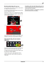
Page 44: ...s of material potentially harmful for the equipment The inversion sequence involves two minutes of air suction and one minute of expulsion at cyclic intervals of 20 seconds of slowing down of the fan speed in order to protect its mechanism Hydraulic blocking of turret rotation optional The buttons shown above are present if said optional device is present on the forklift truck being used To releas...

Page 45: ...indow only from inside the cab turn lever 1 anti clockwise to unlock it Push the window outwards guiding it all the way by holding handle 2 Push further to lock 3 in seat 4 To shut the window turn lever 5 anti clockwise to release the limit stop block Hold the window by means of handle 2 till it is completely closed Turn lever 1 clockwise and make sure the window is locked in the closed position R...

Page 46: ...g suspension of the seat to adjust the preload The adjustment is correct if the numeric indication on the ring nut corresponds approximately to the driver s weight including the clothing Longitudinal position of the seat Use the lever 2 to move the seat in the longitudinal direction With this lever the arm rests and relative controls remain fixed The adjustment is correct if the operator can grip ...

Page 47: ...matic winder may not work properly causing accidents sometimes fatal If necessary consult your dealer to have longer seat belts fitted Always check the fabric of the safety belt the buckle and winder every time before using the vehicle Replace the seat belt or components found to be worn or damaged Fasten the seat belt Pull the seat belt out of the winder with a slow fluid movement to prevent auto...

Page 48: ...lever of the steering column positioned on the right under the ignition key pulling it outwards then adjust the distance after finding the right distance reposition the locking lever On the right hand side under the lever for adjustment of the depth of the steering column depth 2 there are 2 CAN type connectors for control of the diagnostics of the entire vehicle and 1 LAN type connector for trans...

Page 49: ...r the button is released Touching these parts can cause burns The electric cigarette lighter can be used as a 12V power socket To use it as a power socket remove the electric cigarette lighter without pressing it and insert the male cigarette lighter socket supplied with the device to be powered USB socket A USB socket is present under the graphic panel with the function of dialog with the softwar...

Page 50: ...cab floor Press the accelerator pedal to increase the I C engine speed Release the accelerator pedal to decrease the I C engine speed The accelerator pedal 2 is present on the cab floor Press the brake pedal down all the way to stop the vehicle Inching Pedal In the first 20 mm travel the service brake pedal works as the inching pedal The inching pedal works as a clutch making it possible to increa...

Page 51: ...expressly banned by means of signs NOTE the warning buzzer emits a short warning if connected with a radio control optional Windscreen wipers The vehicle has three windscreen wipers The wiper on the rear window is activated separately while those on the upper window and windshield can only be activated simultaneously Controls O all windscreen wipers deactivated I activates intermittent movement of...

Page 52: ...he low beams move the lever down for continuous activation apply slight traction towards the steering wheel to activate the high beam headlights The lever will return immediately to the neutral position when released Horn To use the warning buzzer press the button in the centre at the tip of the lever Do not use the warning buzzer in densely populated spaces or where expressly banned by means of s...

Page 53: ...ts press the relevant button Work lights The button for activation deactivation of the work lights is in the centre of the controls page When the command is activated the button turns blue and the beacon starts working if the command is deactivated the beacon switches off and the button changes to grey Travelling speed The two speed hydrostatic transmission works according to two modes Tortoise mo...

Page 54: ... with parallel axis To change the steering modes Stop the vehicle Display the main page of the multi function display Align the wheels of both axles until the green indicators light up Press the button concerned for the required steering mode Joystick The vehicle is equipped with two joysticks near the driver s seat arm rests The joysticks control the main hydraulic movements of the vehicle To imp...

Page 55: ...k for the correct operating procedures If the roller present on the joystick is activated without the help of the enable button and with the engine switched on pressure in the hydraulic circuit sent to the accessory is discharged Use this procedure before disconnecting the quick fit couplings of the hydraulic circuit of the equipment at the head of the boom Levelling on wheels Levelling on wheels ...

Page 56: ... and lowering of the stabilisers for all models Press on the icons present on the switches to extend the stabilisers retract the stabilisers lift the stabilisers lower the stabilisers Control by means of the multi function display To operate the stabilisers by means of the multiple function display the stabilisers page must be displayed The commands in the page are blocked by default for safety re...

Page 57: ...sed up rapidly Exclusion of the safety systems Exclusion of the safety systems accompanied by inappropriate movements can cause the vehicle to tilt over with risk of accidents and death Do not try to exclude the safety systems to increase the loading capacity of the vehicle Take the key with the metal grip from the safety keys cabinet after breaking the glass using the hammer provided Insert the k...

Page 58: ...ired limit Keep the button corresponding to the function to be limited pressed for 3 seconds Check to make sure the numeric value of the limit is updated Hydraulic movements speed The controls for hydraulic movements speeds adjustment are present in the limits page The buttons available for controlling the hydraulic movements speed are Buttons 1 for turret clockwise and anti clockwise rotation spe...

Page 59: ...uck standard radio control only enables the commands on the forklift truck turret telescopic boom and accessory with the vehicle always stabilised radio control with guidance function in addition to the standard functions this model is provided with forklift truck guidance with certain limitations imposed by the position of the telescopic boom The specific information as regards the technical data...

Page 60: ...om the vehicle with your back to it Always use three gripping points when climbing up or down two hands gripping the handles and one foot on a step or two feet on the steps and one hand gripping the handle Do not climb on or get off when the vehicle is in motion Do not climbor get down from thevehicle carryingtools or other objects Load the tools required before climbing on the vehicle Unload the ...

Page 61: ...he jumper cable ends do not come in contact with one another or with the vehicle Do not smoke in the vicinity of the batteries The electrolyte contained in the batteries is an acid and can cause burns if it comes in contact with the skin and eyes Always wear safety goggles and acid resistant gloves when starting up a vehicle using jumper cables Incorrect connection of jumper cables can cause explo...

Page 62: ...p the oil In case of particularly cold climates more than 5 minutes of heating may be necessary Use this period of time to heat the hydraulic fluid operating the joysticks to raise and lower the telescopic boom Releasing the parking brake To release the vehicle s parking brake follow the criteria given below sit correctly in the seat inside the cab with the engine running check to make sure the ge...

Page 63: ... its two statuses engages and disengages the parking brake in manual mode Whenever the vehicle is switched off the parking brake automatically engages When the vehicle is switched on again the following two conditions occur Brake button on parking brake on in this condition simply move the button to the parking brake off position to disengage the parking brake and be able to move Brake button on p...

Page 64: ...d as sitting for more than 5 seconds and at the same time the forward speed is less than 5 km h If the forward speed is faster than 5 km h the neutral gear is inserted situation controlled by the transmission by applying the maximum possible hydraulic braking and then under this threshold the parking brake is automatically engaged which can be removed once the operator is again detected in the dri...

Page 65: ...y of the vehicle and the ground conditions Slow down on bends Avoid sudden action on the vehicle controls Never operate the vehicle with the load in a position other than that for transport Avoid grounds where there is risk of inclining or overturning the vehicle Use the rear view mirrors frequently Never leave the vehicle unmanned with the engine running Do not bring the vehicle to rest on any st...

Page 66: ...isers Do not try to by pass the safety systems unless strictly necessary for the safety of the vehicle and the operators Do not tamper with the accessory identification systems Do not operate the vehicle with the boom in a position other than for transport Installing the accessory If fitted incorrectly a piece of equipment can suddenly detach from the vehicle during operation This can cause injury...

Page 67: ...if the equipment identified does not correspond to that fitted on the vehicle The vehicle can however be used but the functionality and load capacity are limited for safety reasons If no accessory is fitted on the forklift truck confirm the absence by means of the green validation button Dismantling the accessory Position the vehicle on a stable level surface Make sure there is sufficient space fo...

Page 68: ...ever try to lift loads heavier than the rated capacity of the vehicle The load charts of the accessories are valid for loads with the centre of gravity having a longitudinal distance less than 500 600 mm from the forks heel depending on the rotary vehicle model being used and can be checked by the corresponding load chart shown on the touch screen and in the User Manual of the accessory In case of...

Page 69: ...the reverse gear lever in the neutral position Lift the load 1 slightly and incline the quick fit coupling upwards 2 to make the load stable taking care to avoid modifying the balance negatively If possible lower the load without shifting the vehicle lift the boom to move the load away 3 retract the telescopic boom 4 and lower it to bring the load to the transport position 5 If the load cannot be ...

Page 70: ...ind speed does not exceed 10 m s Check that there is no one in the area between the load and the forklift truck during operations Moving the forklift truck with a hanging load Before starting to move it is advisable to inspect the ground in order to avoid slopes excessive inclinations dips holes and ground that is too soft Make sure that the wind speed does not exceed 35 km h The maximum travellin...

Page 71: ...ors to check for the possible presence of people animals holes obstacles changes in slope etc Visibility on the right side may be reduced when raising the boom so make sure you have a good view of the route before raising the boom and proceeding with operations If visibility while travelling forward is not sufficient enough to guarantee safety due to the size of the load it is advisable to travel ...

Page 72: ... very careful not to move away from the roadside anything buried along the edge of the road could cause the vehicle to overturn or damage some components Surfaces covered with snow or ice are extremely dangerous operate with great caution and reduce the vehicle speed as much as possible In case of snow operate with great caution if the vehicle sinks into the snow there is a risk that it may overtu...

Page 73: ...ush the pin in downwards all the way Hydraulic blocking of turret rotation optional The buttons shown above are present if said optional device is present on the forklift truck being used To release turret rotation press the green button until the shear pin is lifted completely To block turret rotation after aligning the turret press the red button until the shear pin is lowered completely Periodi...

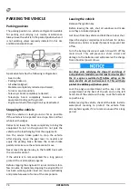
Page 74: ... conductor absent If the vehicle is to remain parked for a long period protect it from atmospheric agents Before stopping the engine let it run at minimum for a few minutes Immediately stopping the engine after it has been working under load can cause overheating and premature wear of some of the components Leaving the vehicle Remove the ignition key Before leaving the cab shut all windows and mak...

Page 75: ...f the country in which it is to be used Consult your dealer for additional information on the matter Observe the general rules on the matter of road travel in force in the country in which the vehicle is to be used While travelling on roads only use the mode with two steering wheels Travel with the telescopic boom completely retracted and lowered as far as possible Make sure that the quick fit cou...

Page 76: ... distances and at speeds not exceeding 10 km h If the vehicle is to be transported for longer distances and at higher speeds use a suitable transport vehicle Before towing the vehicle retract and lower the telescopic boom completely and remove the load Do not use chains for towing the vehicle Use steel cables with rings at the ends or a special rigid tow bar Make sure the cable is in good conditio...

Page 77: ...of the gear in neutral The gear must be positioned manually in case of malfunctioning of its lever because of a hydraulic failure Move under the vehicle near the front axle from the right side Identify the hydrostatic transmission and hydraulic actuator of the gear Disconnect unions 1 and 2 from the actuator and plug the ends of the tubes with suitably sized screw caps Using a tool as lever shift ...

Page 78: ......
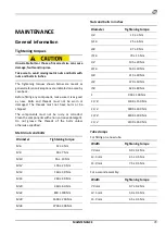
Page 79: ...h a non corrosive detergent Do not grease the threads of the bolts unless otherwise specified Metric nuts and bolts Diameter Tightening torque M6 12 3 Nm M8 28 7 Nm M10 55 10 Nm M12 100 20 Nm M14 160 30 Nm M16 240 40 Nm M20 460 60 Nm M24 800 100 Nm M30 1600 200 Nm M36 2700 300 Nm Nuts and bolts in inches Diameter Tightening torque 1 4 12 3 Nm 5 16 25 6 Nm 3 8 47 9 Nm 7 16 70 15 Nm 1 2 105 20 Nm 9 ...

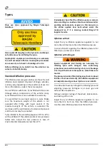
Page 80: ...e works at temperatures below zero Adjust the tyre pressure in case of environmental temperatures less than 0 C Periodically check that the inflation value is correct also according to sensitive climatic variations and or working environments as given in this manual on the sticker applied near each wheel under the mudguard or if it is missing contact Magni TH Support Service Inflation with air Adj...

Page 81: ...tas 4 5 bar 0 45 Mpa 65 psi 14 00 x 19 5 Standard tyre characteristics for RTH 5 18 RTH 5 21 RTH 5 23 RTH 5 25 RTH 6 21 RTH 6 23 RTH 6 25 models Measurement characteristics Make Inflation pressure Rim size 18 R x22 5 445 65 R 22 5 AGP23 169F Aeolus 8 30 bar 0 83 Mpa 120 psi 14 00 x 22 5 18 R x22 5 445 65 R 22 5 AE77 169F Aeolus 8 00 bar 0 80 Mpa 116 psi 14 00 x 22 5 ...

Page 82: ...ectors under the cab at the head of the telescopic boom inside the rear cab compartment on the transducers of the valves on all the micro switches in the vicinity of bonnets and covers fitted with grilles While cleaning the vehicle avoid aiming high pressure water jets directly at the hydraulic hoses inside the turret ...

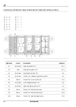
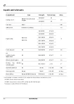
Page 83: ...in gauge rotation manifold encoder 5 A F2 Nut brown Midac Plus 3B6 electronic control unit 5 A F3 Nut brown Touch screen panel timer 5 A F4 Nut brown Vehicle radio 5 A F5 Nut brown GPS setup 5 A F6 Nut brown Setup 5 A F7 Nut brown Cab ceiling light 5 A F8 Nut brown GPS setup 5 A F9 Nut brown Window washing water pump horn 5 A F10 Brown Cab switches 7 5 A ...

Page 84: ...s 10 A F20 Red Trailer socket 10 A F21 Blue Front cab work lights 15 A F22 Blue Midac Plus 3B6 control unit power output 15 A F23 Blue Rear cab work lights 15 A F24 Blue Autec radio control 15 A F25 Blue Upper windscreen wiper 15 A F26 Blue Front windscreen wiper 15 A F27 Blue Rear windscreen wiper 15 A F28 Blue Cigarette lighter 15 A F29 White Master Cabletronic control unit 25 A F30 White Boom h...

Page 85: ...onditioning tap opening 10 A R11 Air conditioning tap closing 10 A R12 Front windscreen wiper intermittence 10 A R13 Front windscreen wiper 1 speed 10 A R14 Front windscreen wiper 2 speed 10 A R15 Upper windscreen wiper 1 speed 10 A R16 Rear windscreen wiper 1 speed 10 A R17 Locked up vehicle radio power supply 10 A KT18 Touch screen panel timer KT19 Windscreen wipers intermittence function ...

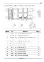
Page 86: ...itive 30 10 A F3 Nut brown Hydromotor positive 15 5 A F4 Nut brown Positive 15 stabilisers proximity switches 5 A F5 Brown Positive 15 turret control unit 7 5 A F6 Nut brown Left road lights positive 15 5 A F7 Nut brown Right road lights positive 15 5 A F8 Brown Positive 15 left side low beams 7 5 A F9 Brown Positive 15 left side high beams 7 5 A F10 Brown Positive 15 right side high beams 7 5 A ...

Page 87: ...15 available in chassis plant line 10 A F22 Red Positive 30 available in chassis plant line 10 A F23 Red Positive 15 stop lights 10 A F24 Blue Positive 15 setup 15 A F25 Yellow Positive 15 power supply 30 R5 20 A F26 Yellow Positive 15 electric fan 2 oil radiator 20 A F27 Yellow Positive 15 electric fan 1 oil radiator 20 A F28 Yellow Positive 15 B54 B56 NOx sensors 15 A F29 Yellow Positive 15 Cabl...

Page 88: ...c fluid electric fan 2 relay 20 A R4 Hydraulic fluid electric fan 1 relay 20 A R5 Road lights relay 20 A R6 Stabilisers descent function negative cut off relay 20 A R7 STOP lights relay 10 A R8 Available 10 A R9 Slow fast speed change relay 10 A R10 Engine reset relay 10 A R11 Available relay 10 A R12 Reversing lights and buzzer relay 10 A R13 Heated urea tubes main power supply relay DEUTZ 40 A R...

Page 89: ...consent relay Neutral position at EDC17 CV54 5 A F4 Nut brown Positive 15 stabilisers proximity switches 5 A F5 Nut brown Positive 15 Bosch Rexroth control unit electronics 5 A F6 Nut brown Positive 15 left side road lights 5 A F7 Nut brown Positive 15 right side road lights 5 A F8 Brown Positive 15 left side low beams 7 5 A F9 Brown Positive 15 left side high beams 7 5 A F10 Brown Positive 15 rig...

Page 90: ... 10 A F24 Blue Positive 15 Bosch Rexroth control unit output 15 A F25 Yellow Positive 15 air compressor fan 20 A F26 Yellow Positive 15 electric fan 1 oil radiator 20 A F27 Yellow Positive 15 electric fan 2 oil radiator 20 A F28 Blue Positive 15 available in chassis plant line 15 A F29 Yellow Positive 15 Cabletronic chassis expansion control unit 20 A F30 White Positive 15 Cabletronic chassis slav...

Page 91: ...20 A R7 Stop lights relay 10 A R8 Relay Feedback for parking brake bistable 10 A R9 Slow fast speed change relay 10 A R10 DEUTZ engine control unit Neutral position relay EDC17 CV54 10 A R11 Engine line setup relay engine reset if necessary 10 A R12 Reversing lights and buzzer relay 10 A R13 Setup relay to chassis line possible heating of urea pipes 40 A R14 Fuel pump activation relay 20 A ...

Page 92: ...8 2 8 Front rear axles differentials Oil SAE 85W90 27 77 11 Wheel reduction gears Oil SAE 85W90 27 77 1 6 Slewing ring rotation reduction gear Oil ISO VG 150 175 2a Hydraulic fluid tank Oil ISO 46 15 130 180 Greasing points Grease NGLI 2 30 120 as requ Boom sliding Grease KERNITE Delavan PTFE NLGI 2 20 150 as requ The percentages correspond in the order to the composition of the antifreeze distill...

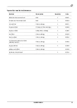
Page 93: ...tridge 1 09371 Engine air filter Primary air filter cartridge 1 24069 Engine air filter Safety filter cartridge 1 12684 Fuel filter Filter cartridge 1 24309 Fuel pre filter Filter cartridge 1 24293 Transmission hydraulic oil filter delivery suction Filter cartridge 1 23094 Engine oil filter Filter cartridge 1 24289 AdBlue pump filter Filter cartridge 33204 Hydraulic oil tank bleed 1 12734 ...

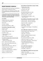
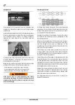
Page 94: ... rotation slewing ring gear lubrication Wheels check tightening of nuts Stabilisers lubrication of pins Every 250 hours of operation or every 3 months Telescopic boom chains checking and lubrication Transmission belt check Differentials oil check Two speed reduction gear oil check Wheel reduction gear oil check Steering elements lubrication Turret rotation slewing ring gear check reduction gear oi...

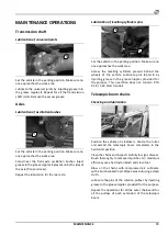
Page 95: ...pproaches the work area Access the levelling cylinders present behind the wheels of the vehicle Lubricate pins 2 and 3 by injecting grease in the grease nipples provided for the purpose This operation does not concern RTH 5 18 5 18 Smart models Telescopic boom chains Checking and lubrication Position the vehicle on stabilisers Centre the turret and extend the telescopic boom completely in the hori...

Page 96: ...xtension must be known Take measurements of a new chain or contact your dealer for this information Position the vehicle on stabilisers Centre the turret and extend the telescopic boom completely in the horizontal position Measure the lengthening of the chain due to wear Take the measurements on sections with 15 18 links Use the heads of the pins as reference If the lengthening of any of the secti...

Page 97: ...ing the position of the indicator arm 1 Read the value measured on the intersection point arrow scale 5 and indicator arm 1 Correct the tension if necessary and repeat the measurement The belt tension tester can be ordered through the Customer Service Replacement 1 screw 2 screw 3 screw 4 adjuster wrench To replace the transmission belt loosen the screw and lock nut move the generator above the ad...

Page 98: ... engine Place a container under the drain screw unscrew the latter and drain out the lubricant oil After draining reposition the screw with a new sealing ring and tighten by applying a 55 Nm torque Fill lubricant oil warm the engine to a temperature 80 C and check the lubricant oil level Top up if necessary Replacing the lubrication oil cartridge Loosen the filter using the tool and unscrew it Col...

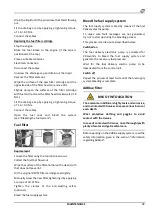
Page 99: ...al DEUTZ filter cartridge seal slightly Manually screw the new filter tightening it by applying a torque of 10 12 Nm Tighten the clamps of the anti twisting safety optional Bleed the fuel supply system Bleed the fuel supply system The fuel supply system is bled by means of the fuel delivery electric pump To make sure fault messages are not generated try not to start up during the bleeding process ...

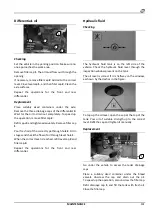
Page 100: ...ture with the engine switched on When the cap is removed the liquid may flow out violently and cause serious burns Make sure the engine is cold before working on the cooling system Checking Set the vehicle in the parking position Check the level in the expansion tank placed above the radiator The level is correct when it is half way on the inspection window Open the tank check the coolant additive...

Page 101: ...s and check the flow of oil through level hole 1 When the correct level is reached refit level cap 2 and filler cap 3 Repeat the operations for the front and rear differential Hydraulic fluid Checking The hydraulic fluid tank is on the left side of the vehicle Check the hydraulic fluid level through the inspection window present on the tank The oil level is correct if it is halfway on the window a...

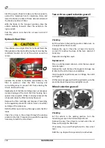
Page 102: ...tory standards in force Insert a new filter cartridge of the same type Refit the filter cover Start up the engine and check for leaks Check for a drop in the oil level through the window present onthe tank if required topupwiththe quantity necessary to reach the correct level Two or three speed reduction gear oil Checking Set the vehicle in the parking position Make sure no one approaches the work...

Page 103: ...ng to the schedule indicated in this Manual Do not try to wash dirty filters If the vehicle is expected to be used in environments with a lot of dust or high concentrations of contaminating or polluting agents in the air halve the time interval between one filter replacement and the next Replacing the primary cartridge Set the vehicle in the parking position Rotate the turret to the left through 4...

Page 104: ...sence of a sufficient layer of grease on the sliding surfaces and on the sliding blocks Lubrication Park the vehicle in a suitably sized area and rest the stabilisers on the ground Remove the equipment from the quick fit coupling Centre the turret and set the telescopic boom in the horizontal position Extend the telescopic boom completely Clean all the sliding surfaces thoroughly Using a brush app...

Page 105: ...f the boom Always try to adjust the sliding blocks symmetrically so that each stage is centred with respect to the adjacent ones After completing the operations try to extend and retract the boom to check the boom movement is smooth If the movement of the boom is not smooth repeat the adjustments unscrewing the screws through one complete turn instead of through half a turn Contact your dealer for...

Page 106: ...end and lift the telescopic boom Switch off the engine and turn the ignition key to position I Press and hold down switch 1 Retract and lower the boom to check the correct working of the emergency hydraulic pump In case of a fault in the emergency hydraulic circuit avoid using the vehicle and contact your dealer Engine radiator Cleaning To remove dust and debris from the radiator mass compressed a...

Page 107: ...crews of the slewing ring gear on the chassis align hole 5 with the screw underneath by rotating the turret Tighten the screws by applying a 570 Nm torque Repeat the operation for each screw rotating the turret from time to time Checking reduction gear oil Retract and lift the telescopic boom completely Rotate the turret to the left by about 60 for better access to the reduction gear Check the hyd...

Page 108: ... grease uniformly Remove the excess grease Lubricate all the rotation pins of the stabilisers including the pins of the hydraulic cylinders Lubricate by injecting grease in the grease nipples present on each pin Wipe excess grease to prevent accumulation of dirt Operate the hydraulic movement of the stabilisers a number of times to distribute the grease uniformly Make sure the stabiliser foot osci...

Page 109: ... tank to rinse out impurities that may be present at the bottom Close and tighten drainage cap 3 Fill the tank with clean fuel Check to make sure there are no leaks Window washing liquid tank Filling Open the compartment in the rear part of the cab to access the window washing liquid tank housing Unscrew the cap by turning it anti clockwise Fill the tank with window washing liquid leaving about 1 ...

Page 110: ...ic movements e g boom and stabilisers not allowed Carry out the hydraulic movements separately Stabilisers microswitch error Inconsistency between main switch of stabilisers and redundant Check errors in alarms page Boom ascent limit stop Mechanical limit stop of boom ascent has been reached Do not insist with the command Parking brake applied Attempt to move on wheels with parking brake applied D...

Page 111: ...e the operating mode Emergency pump activated Emergency hydraulic pump activated warning No action required Press dead man s joystick Hydraulic command given by means of joystick without pressing movement enable button Press the movement enable button to confirm voluntary activation of command Radio control ON Hydraulic command given from cab with radio control active Disconnect the radio control ...

Page 112: ... correct fuel Suction or discharge system obstructed Visually inspect the suction and discharge and remove any obstructions present Replace the air filter if necessary Fuel return line blocked Check to make sure the line is clear and connected to the upper part of the tank Fault in one or more injectors Check the electrical connections ECU or sensors fault Check the electrical connections Engine D...

Page 113: ... Check for blockage along the line Check the state of the filters and replace if necessary Fuel return line blocked Check to make sure the line is clear and connected to the upper part of the tank ECU or sensors fault Check the electrical connections Engine irregular operation Cause Solution Engine cold or coolant temperature sensor fault Check the sensor electrical connection Check the working of...

Page 114: ...ne with correct fuel Incorrect adjustment of valve play Correct the adjustment Make sure the rod and equaliser mechanism is not damaged or worn Noise coming from engine block Contact your dealer immediately Engine reduced power Cause Solution No fuel in tank Refuel Oil level not correct Check the level Engine overload Check the presence of overloads due to faulty auxiliary parts Fuel dirty or non ...

Page 115: ...ssion ratio Engine Does not reach the maximum rpm Cause Solution Speedometer defective Check the engine speed using a manual speedometer Correct if necessary Engine overload Check the presence of overloads due to faulty auxiliary parts Fuel dirty or non conforming SWITCH THE ENGINE OFF Replace the fuel filters Run the engine with correct fuel Wastegate valve actuator diaphragm cracked Repair or re...

Page 116: ...k fumes at the exhaust Cause Solution Suction or discharge system obstructed Visually inspect the suction and discharge and remove any obstructions present Replace the air filter if necessary Leaks between the turbocompressor and suction manifold Inspect and repair the leaks Intercooler defective Check the radiator mass Leaks from discharge manifolds or from turbocompressor Repair the leaks from t...

Page 117: ...y standards are provided with special control software for limiting their working until they are switched off for precautionary purposes if there are problems in the UREA AdBlue purification systems Specifically the problems can be summarised as follows low level of urea in tank poor quality of urea liquid tampering with the urea system system errors Depending on the extent of the anomaly in order...

Page 118: ... Flashing acoustic signal Level 2 Level 2 Efficiency of catalyst AdBlue quality If the efficiency of the catalyst is too low yield percentage even if the level has already been topped up warning messages are sent to the SCR function or optional CAN display The warning signals are also transmitted if an unsuitable reducing agent is used Efficiency of catalyst AdBlue quality SCR indicator light Engi...

Page 119: ...components including an implausible value of Nox level or temperature sensor If the AdBlue injection cycle is affected by a system error the power is reduced System errors SCR indicator light Engine indicator light Power reduction Recognised Acoustic signal permanent light Flashing None Recognised 10 min Acoustic signal permanent light Flashing Level 2 In power limitation condition the forklift tr...

Page 120: ...e guides Contact your dealer Control unit defective Contact your dealer Fault in one or more injectors Check the electrical connections Lubricant excessive consumption Cause Solution Oil leaks Check the engine for leaks Lubricant specifications unsuitable Make sure a suitable lubricant is used Check contamination by fuel Leaks in cooling system Check for the presence of lubricating oil in the cool...

Page 121: ...act your dealer Oil pump worn Contact your dealer Lubricant excessive pressure Cause Solution Lubricant specifications unsuitable Make sure a suitable lubricant is used Check contamination by fuel Pressure gauge fault Check the correct working The oil pump pressure limiter valve is blocked in the closed position Contact your dealer Coolant leaks Cause Solution Coolant level not correct Check the l...

Page 122: ... concentration of anti freeze Drain part of the circuit and fill with distilled water Temperature sensor defective Check the accuracy of the sensor Thermostat faulty or missing Check replace the thermostat Coolant pump faulty Check replace the pump Passage of liquid through the radiator head or engine block obstructed Wash the plant with distilled water and fill with fresh coolant Coolant not at r...

Page 123: ...t tensioner device in the transmission belt Do not dismantle the transmission belt completely Reusing the vehicle Clean the fuel tank Refuel Replace the fuel prefilter and filter Check the coolant level If topping up is necessary take a sample of the liquid and check the composition Add distilled water or pure liquid to adjust the composition Check the battery charge Charge if necessary Check the ...

Page 124: ...roved contact the dealer or the Customer Service directly Some equipment produced by other manufacturers can be adapted for fitting on the vehicles described in this Manual Contact your dealer to know if your equipment can be adapted for assembly on your vehicle If the equipment is suitable and before proceeding the equipment and the vehicle must be sent to the dealer for the required modification...

Page 125: ...________________________________ _________________________________________________________________________________ Street ____________________________________________________________________________ Post code City Town _________________________________________ province ________________ represented by Mr __________________________________________________________________ according to the conditions ...

Page 126: ...t the transfer has been reported to the relevant Bodies local INAIL The Dealer The Buyer ___________________ ________________ Register of change of ownership on ____________________ The ownership of the vehicle identified in this Register was transferred to Company ______________________________________ represented by Mr _________________________ Street No _________________________________________...

Page 127: ...t the transfer has been reported to the relevant Bodies local INAIL The Dealer The Buyer ___________________ ________________ Register of change of ownership on ____________________ The ownership of the vehicle identified in this Register was transferred to Company ______________________________________ represented by Mr _________________________ Street No _________________________________________...

Reviews: